HT-ST9
29
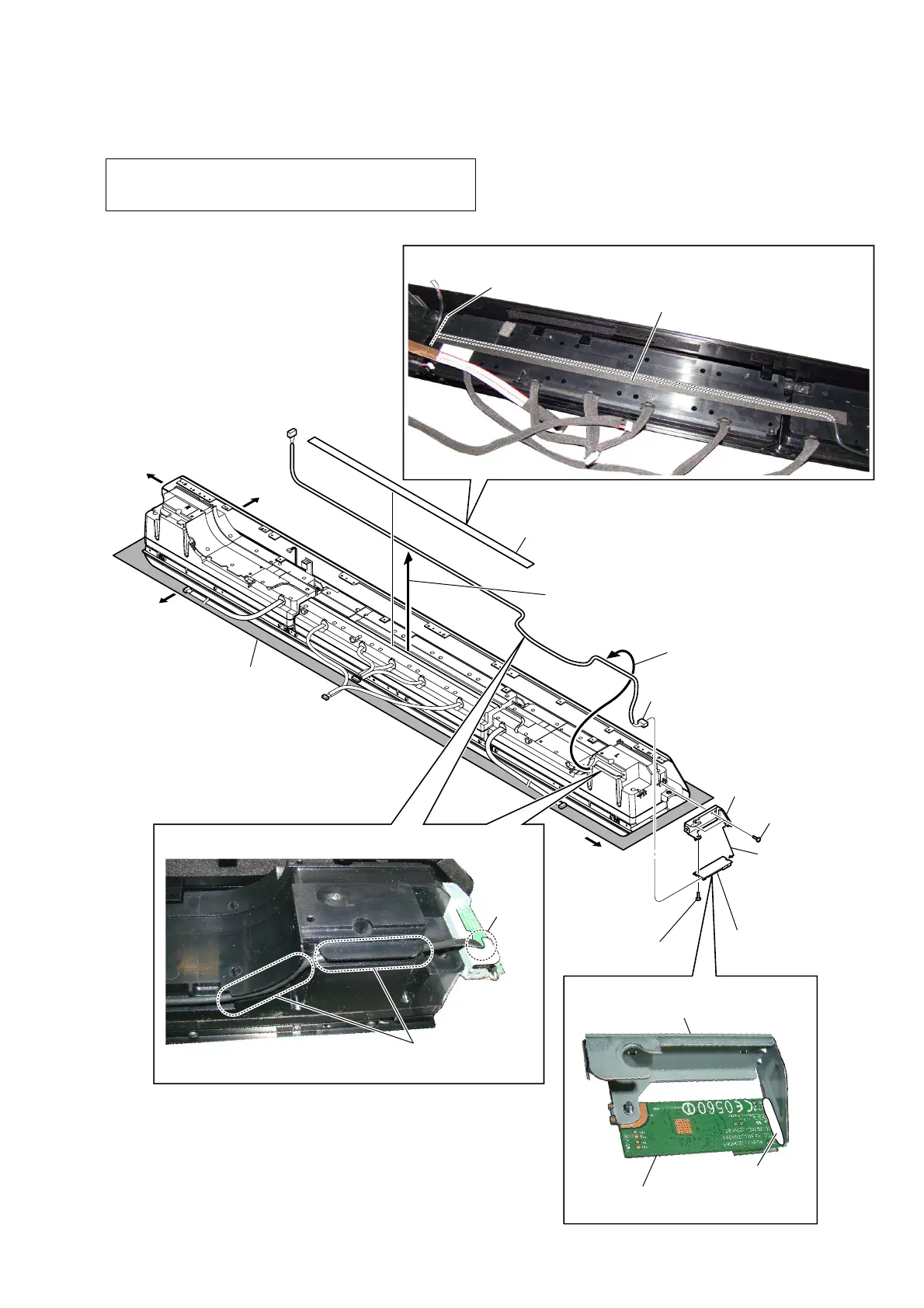
2-20. CARD WLAN/BT COMBO (WIFI1)
Note 1: When the card WLAN/BT combo is replaced, refer to “NOTE
OF REPLACING THE COMPLETE MB1406 BOARD OR
CARD WLAN/BT COMBO” on page 6.
guide line
,QVWDOODWLRQSRVLWLRQRIWKHFXVKLRQZLUH:,),
cushion (wire WIFI)
–7RSYLHZ–
–5HDUYLHZ–
Note 2:
Lay a soft piece of cloth
under the unit to avoid
damaging the grille assy.
5 two screws
(BVTP3 u 8)
6 screw
(BVTP3 u 8)
1 cushion (wire WIFI)
2 Draw the WIFI/BT wire
out of the groove.
4 connector
8 bracket (WIFI)
bracket (WIFI)
9 card WLAN/BT combo
(WIFI1)
card WLAN/BT combo
(WIFI1)
:,),%7ZLUHVHWWLQJ
Note 3:
When installing the WIFI/BT wire,
pressed into the groove.
groove
3 Draw the WIFI/BT wire
out of the groove.
Right side
Top side
Left side
Bottom side
7
Remove the card
WLAN/BT combo
(WIFI1) in the
direction of the
arrow.
bond
$SSOLFDWLRQSRVLWLRQRIWKHERQG
 Loading...