HT-ST9
23
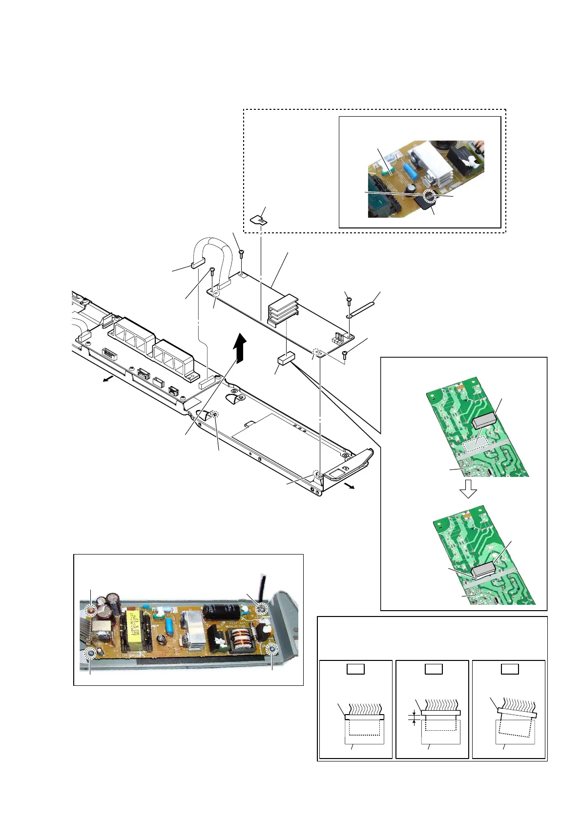
2-14. POWER BOARD
Insert only part way.Insert straight into
the interior.
connector
Insert at a slant.
connector
connector
connector
connector connector
OK NG NG
How to install the connector
Insert the connector straight into the interior.
There is a possibility that using this unit without
the connector correctly installed will damage it.
(Except US, CND, TW)
7 cushion (Z)
1 connector
(CN7001)
3 screw
(BVTP3 u 8)
2 screw
(BV3 u 8 CU)
– Chassis block rear view –
3 screw
(BVTP3 u 8)
3 screw
(BVTP3 u 8)
4 wiring stopper
6 sheet
(insulation JW905)
sheet (insulation JW905)
POWER board
JW905
bond
,nstallation position oI the cXshion (=)
cushion (Z)
POWER board
Fix with the bond.
cushion (Z)
POWER board
,nstallation position oI
the sheet (insXlation -W)
5 Remove the POWER board block
in the direction of the arrow.
Bottom side
Left side
guide pin
hole
hole
guide pin
8 POWER board
Note 1:
When installing the POWER board, align
the two guide pins and two holes.
Note 2:
When installing screws, follow the installing procedure
in the numerical order given.
1
4
2
3
Ver. 1.1
 Loading...