Engine General Information and Diagnosis: 1A-104
DTC P0131 / P0132 / P0134: O2 Sensor (HO2S) Circuit Low Voltage / High Voltage / No Activity
Detected (Sensor-1)
S5JB0A1104032
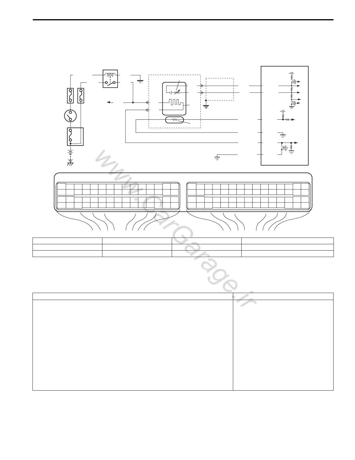
Wiring Diagram
A/F Sensor Description
Refer to “A/F Sensor Description: ”.
DTC Detecting Condition and Trouble Area
E23 C37
34
1819
5671011
1720
47 46495051
2122
52
1625
9
24
14
29
5557 54 53
59
60 58
2
262728
15
30
56 48
32 31343536374042 39 38
44
45 43 41 33
11213
23
834
1819
5671011
1720
47 46495051
2122
52
1625
9
24
14
29
5557 54 53
59
60 58
2
262728
15
30
56 48
32 31343536374042 39 38
44
45 43 41 33
11213
23
8
4
3
9
PNK
6
2
1
8
5
BLK/WHT
BLK
PNK*GRN
C37-34
C37-32
C37-37
C37-38
BLK
BLK
BLU
WHT
C37-35
C37-31
WHT
BLK
RED/YEL
RED/BLU
PNK/BLU
BLK/YEL
10
7
11
5 V
5 V
I5JB0A110044-02
1. HO2 heater relay 4. “O2 HTR” fuse 7. Heater 10. Adjusting resistor
2. Shield wire 5. “IG COIL” fuse 8. To HO2S-2 heater 11. Sensor
3. Ignition switch 6. A/F sensor 9. ECM *: For M16 engine
DTC detecting condition Trouble area
DTC P0131:
A/F sensor (LF+) terminal voltage is lower than specified range or A/F sensor
output current is lower than specification.
(2 driving cycle detection logic)
DTC P0132:
A/F sensor (LF+) terminal voltage is higher than specified range or A/F sensor
output current is more than specification.
(2 driving cycle detection logic)
DTC P0134:
Impedance of A/F sensor element is higher than specification for more than
160 sec even though A/F sensor heater is turned ON for more than specified
time with engine running. (A/F sensor or sensor circuit open)
(2 driving cycle detection logic)
• A/F sensor circuit
• A/F sensor
•ECM

 Loading...


