Engine General Information and Diagnosis: 1A-72
DTC P0101: Mass Air Flow Circuit Range / Performance
S5JB0A1104017
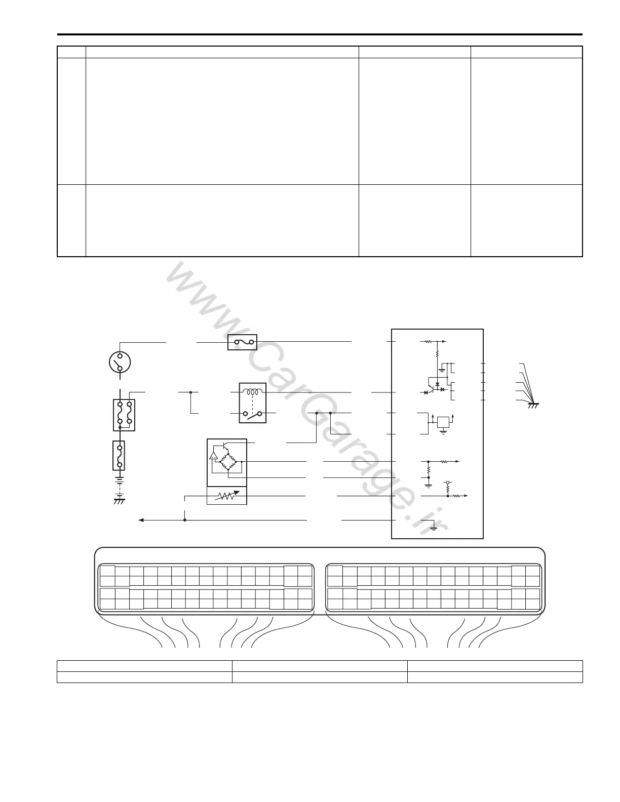
Wiring Diagram
10 HO2S heater control circuit check
1) Disconnect connector from ECM with ignition switch
turned OFF.
2) Check for proper connection of HO2S-2 heater circuit
terminal to ECM connector.
3) If connection are OK, measure wire resistance of sensor
heater control circuit at ECM connector between ECM to
HO2S-2.
Is measured wire resistance lower than 1
Ω
?
Go to Step 11. Repair or replace
defective wire circuit.
11 HO2S-2 heater circuit check
1) Measure insulation resistance between control terminal
of HO2S-2 heater at ECM connector and vehicle body
ground.
Is measured resistance infinity?
Substitute a known
good ECM and recheck.
Repair or replace short
wire.
Step Action Yes No
E23 C37
34
1819
5671011
1720
47 46495051
2122
52
1625
9
24
14
29
5557 54 53
59
60 58
2
262728
15
30
56 48
32 31343536374042 39 38
44
45 43 41 33
11213
23
834
1819
5671011
1720
47 46495051
2122
52
1625
9
24
14
29
5557 54 53
59
60 58
2
262728
15
30
56 48
32 31343536374042 39 38
44
45 43 41 33
11213
23
8
BLK/WHT
BLU/BLK
BLU/BLK
WHT/GRN
BLK/RED BLK/RED
BLK/RED
BLK/YEL
BLU
12V
5V
5V
2
3
4
E23-29
E23-1
E23-60
BLU/BLK
E23-16
LT GRN
GRY/GRN
GRY/GRN
1
BLU/BLK
C37-25
C37-57
5
BLU
RED
C37-26
C37-27
C37-15
C37-29
C37-48
BLK/ORN
C37-58
C37-30
BLK/ORN
BLK/YEL
BLK/YEL
BLK/YEL
I5JB0A110033-01
1. MAF and IAT sensor 3. Main relay 5. To other sensors
2. Ignition switch 4. ECM

 Loading...


