Engine Mechanical: For J20 Engine 1D-101
d) Tighten cylinder head bolts (M10) to 52 N⋅m (5.2
kgf-m, 38.0 lb-ft) according to numerical order in
figure.
e) In the same manner as in step b), retighten
cylinder head bolts (M10) to 103 N⋅m (10.3 kgf-
m, 74.5 lb-ft).
f) Tighten cylinder head bolt (M6) to specified
torque.
Tightening torque
Cylinder head bolt (M10) (a): Tighten 52 N⋅m
(5.2 kgf-m, 38.0 lb-ft), 82 N⋅m (8.2 kgf-m, 59.5
lb-ft), 0 N⋅m (0 kgf-m, 0 lb-ft), 52 N⋅m (5.2 kgf-
m, 38.0 lb-ft) and 103 N⋅m (10.3 kgf-m, 74.5 lb-
ft) by the specified procedure.
Cylinder head bolt (M6) (b): 11 N·m (1.1 kgf-
m, 8.0 lb-ft)
6) Install camshafts and tappets and shims. Refer to
“Camshafts, Tappet and Shim Removal and
Installation: For J20 Engine” for installation.
7) Install 1st timing chain. Refer to “1st Timing Chain
and Chain Tensioner Removal and Installation: For
J20 Engine” for installation.
8) Install 2nd timing chain. Refer to “2nd Timing Chain
and Chain Tensioner Removal and Installation: For
J20 Engine” for installation.
9) Install timing chain cover. Refer to “Timing Chain
Cover Removal and Installation: For J20 Engine” for
installation.
10) Check intake and exhaust valve lashes referring to
“Valve Lash (Clearance) Inspection: For J20
Engine”.
11) Install cylinder head cover referring to “Cylinder
Head Cover Removal and Installation: For J20
Engine”.
12) Install oil pan referring to “Oil Pan and Oil Pump
Strainer Removal and Installation: For J20 Engine in
Section 1E”.
13) Install engine assembly to vehicle referring to
“Engine Assembly Removal and Installation: For J20
Engine”.
Valves and Cylinder Head Disassembly and
Assembly
S5JB0A1426034
Disassembly
1) When servicing cylinder head, remove intake
manifold, injectors, exhaust manifold and water
outlet cap from cylinder head.
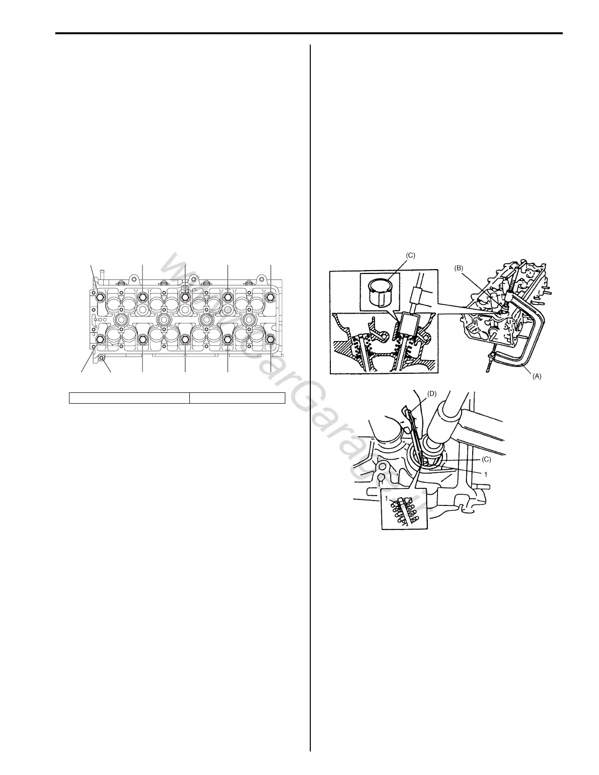
2) Using special tools, compress valve springs and
then remove valve cotters (1) also by using special
tool.
Special tool
(A): 09916–14510
(B): 09916–16510
(C): 09919–28610
(D): 09916–84511
1. Crankshaft pulley side 2. Flywheel side
“7”, (a)
“9”, (a) 3, “11”, (b) “4”, (a) “2”, (a) “6”, (a) “8”, (a)
“5”, (a) “1”, (a) “3”, (a) “10”, (a)
I5JB0A142044-02
I5JB0A142045-01

 Loading...


