Engine General Information and Diagnosis: 1A-150
DTC P0500: Vehicle Speed Sensor (VSS) Malfunction
S5JB0A1104049
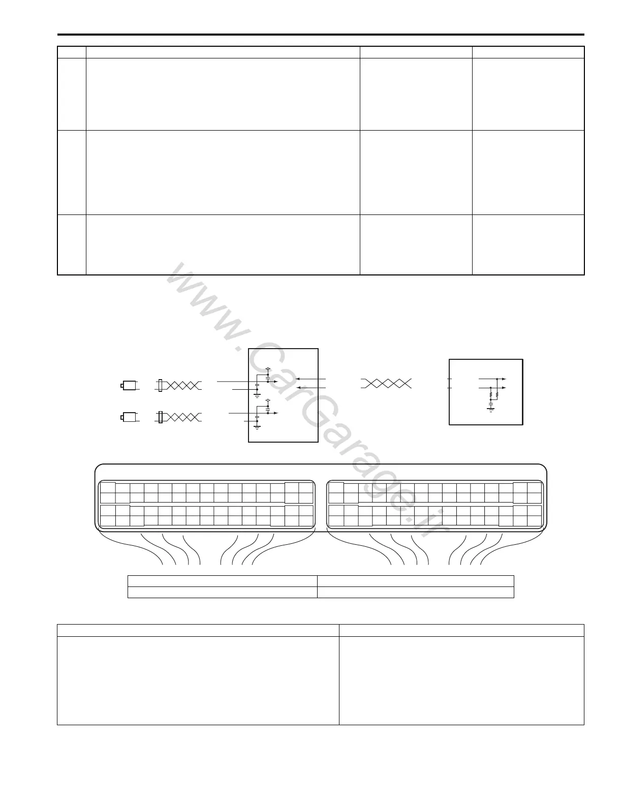
Wiring Diagram
DTC Detecting Condition and Trouble Area
18 Wire circuit check
1) Measure voltage between “RED/YEL” wire terminal of
radiator cooling fan relay No.3 connector and vehicle
body ground with ignition switch turned ON.
Is voltage 0 V?
Go to Step 19. “RED/YEL” wire is
shorted to other circuit.
19 Wire circuit check
1) Measure resistance between “RED/YEL” wire terminal of
radiator cooling fan relay No.3 connector and “E23-48”
terminal of ECM connector with ignition switch turned
OFF.
Is resistance below 5
Ω
?
Go to Step 20. “RED/YEL” wire is open
circuit
20 Radiator cooling fan relay check
1) Check radiator cooling fan relay referring to “Radiator
Cooling Fan Relay Inspection: in Section 1F”.
Is it in good condition?
Substitute a known-
good ECM and recheck.
Replace relay.
Step Action Yes No
E23-4
E23-19
WHT/RED
WHT/BLU
WHT/RED
WHT/BLU
E23 C37
34
1819
5671011
1720
47 46495051
2122
52
1625
9
24
14
29
5557 54 53
59
60 58
2
262728
15
30
56 48
32 31343536374042 39 38
44
45 43 41 33
11213
23
834
1819
5671011
1720
47 46495051
2122
52
1625
9
24
14
29
5557 54 53
59
60 58
2
262728
15
30
56 48
32 31343536374042 39 38
44
45 43 41 33
11213
23
8
BLK
WHT
BLK
WHT
YEL/BLK
YEL
LT GRN
LT GRN/BLK
12V
12V
1
2
3
4
I5JB0A110060-03
1. Rear left side wheel speed sensor (VSS 1) 3. ABS hydraulic unit / control module Assembly
2. Rear right side wheel speed sensor (VSS 2) 4. ECM
DTC detecting condition Trouble area
• Vehicle speed signal is not input while fuel is cut at
deceleration for 4 seconds continuously at 3600 rpm or
less.
• Vehicle speed signal is not input even if engine is running
with more than 3700 rpm at D-Range for 4 sec. (for A/T
model).
(2 driving cycle detection logic)
• Wheel speed sensor (VSS)
• Wheel speed sensor circuit
• ABS hydraulic unit / control module assembly
•ECM

 Loading...


