1A-161 Engine General Information and Diagnosis:
DTC P0620: Generator Control Circuit
S5JB0A1104090
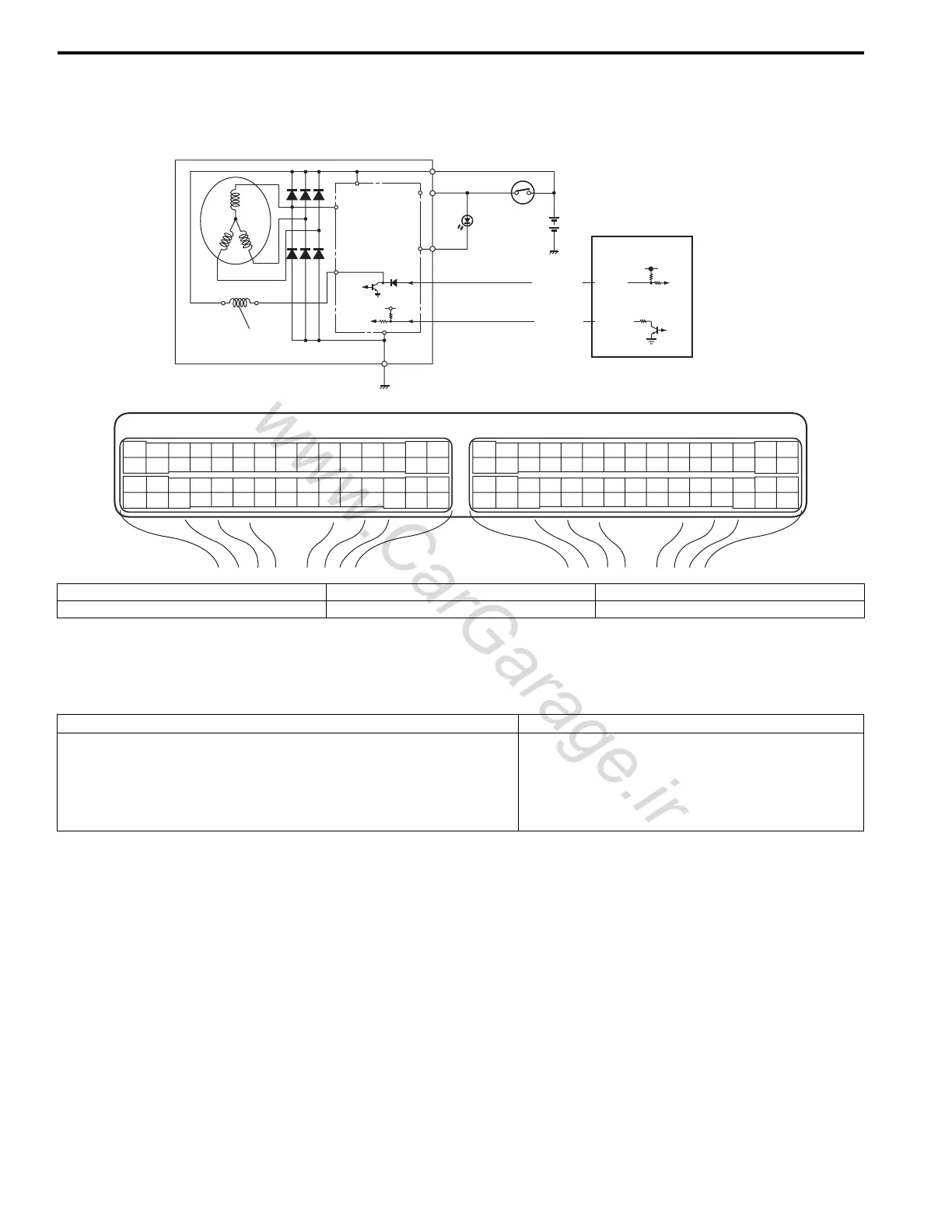
System and Wiring Diagram
Generator Control System Description
Refer to “Generator Control System Description: ”.
DTC Detecting Condition and Trouble Area
DTC Confirmation Procedure
1) With ignition switch turned OFF, connect scan tool to DLC
2) Turn ON ignition switch and clear DTC.
3) Make sure that all accessory switches are tuned OFF.
4) Start engine and warm it up to normal operating temperature (ECT approx. 90 – 95 °C, 193 – 203 °F).
5) Turn ON the following accessory switches.
• Head light switch.
• Blower motor switch (max position).
• Rear defogger switch.
6) Increase engine speed to 4000 rpm and keep it for 10 sec or more.
7) Decrease engine speed to idle.
8) Check DTC and pending DTC.
IG
L
C
FR
E
4
2
BRN/BLK
C37-8
BRN/BLK
C37-28
B
E23 C37
34
1819
5671011
1720
47 46495051
2122
52
1625
9
24
14
29
5557 54 53
59
60 58
2
262728
15
30
56 48
32 31343536374042 39 38
44
45 43 41 33
11213
23
834
1819
5671011
1720
47 46495051
2122
52
1625
9
24
14
29
5557 54 53
59
60 58
2
262728
15
30
56 48
32 31343536374042 39 38
44
45 43 41 33
11213
23
8
1
3
5
I5JB0A110063-01
1. Generator 3. Field coil 5. Ignition switch
2. IC regulator 4. ECM 6. Charge lamp
DTC detecting condition Trouble area
• Battery voltage is higher than specification even through
generator control is maximum regulation (duty 100%).
• Battery voltage is lower than specification even through
generator control is minimum regulation (duty 0%) and electric
load is less than 20 A.
Generator and/or its circuit
Electric load current sensor (for J20 engine)
ECM

 Loading...


