1A-167 Engine General Information and Diagnosis:
DTC P1501 / P1502: Electric Load Current Sensor Circuit Low / High
S5JB0A1104093
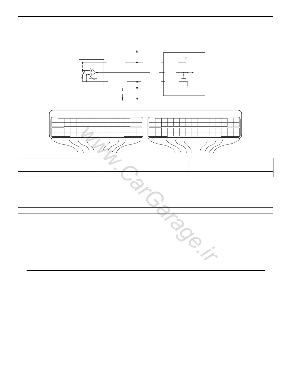
System and Wiring Diagram
Electric Load Current Sensor Description
Refer to “Generator Control System Description: ”.
DTC Detecting Condition and Trouble Area
NOTE
When DTC P0107 and P0532 are indicated together, it is possible that “GRY/RED” wire circuit open.
DTC Confirmation Procedure
1) With ignition switch turned OFF, connect scan tool to DLC.
2) Turn ON ignition switch and clear DTC.
3) Make sure that all accessory switch is tuned OFF.
4) Start engine and warm it up to normal operating temperature (ECT approx. 90 – 95 °C, 193 – 203 °F).
5) Increase engine speed to 3000 rpm.
6) In this state, Turn ON following accessory switch.
• Head lights switch.
• Blower motor switch (max position).
• Rear defogger switch.
7) Decrease engine speed to idle.
8) Check DTC and pending DTC.
1
C37-9
BLU
GRN
GRY/GRN
GRY/GRN
C37-14
GRY/RED
GRY/RED
E23 C37
34
1819
5671011
1720
47 46495051
2122
52
1625
9
24
14
29
5557 54 53
59
60 58
2
262728
15
30
56 48
32 31343536374042 39 38
44
45 43 41 33
11213
23
834
1819
5671011
1720
47 46495051
2122
52
1625
9
24
14
29
5557 54 53
59
60 58
2
262728
15
30
56 48
32 31343536374042 39 38
44
45 43 41 33
11213
23
8
GRY/GRN
5V
2
3
4
5
C37-57
I5JB0A110065-01
1. Electric load current sensor 3. To other sensors (MAP, CO adjust resister (if
equipped), A/C refrigerant pressure (if
equipped)
5. To other sensors (IAT, ECT, MAP, CO adjust
resister (if equipped), A/C refrigerant pressure
(if equipped)
2. ECM 4. To HO2S-2
DTC detecting condition Trouble area
P1501:
Electric load current sensor circuit voltage is lower than specified
range.
P1502:
Electric load current sensor circuit voltage is higher than specified
range.
Electric load current sensor and/or its circuit
ECM

 Loading...


