1H-3 Ignition System:
Component Location
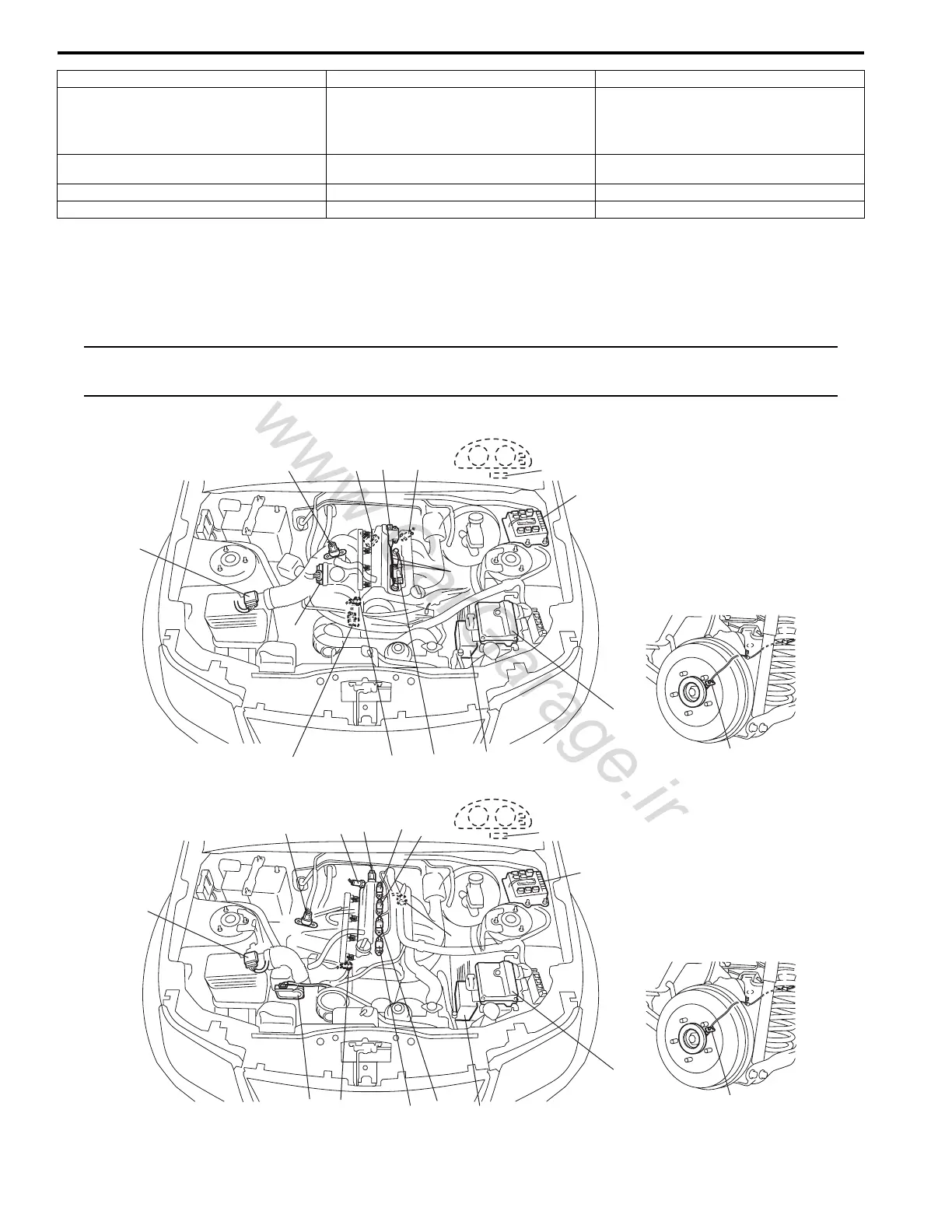
Ignition System Components Location
S5JB0A1803001
NOTE
The figure shows left-hand steering vehicle. For right-hand steering vehicle, parts with (*) are installed
at the opposite side.
2. Main relay 10. No.4 spark plug 18. Ignition coil assembly for No.1
3. Ignition coil assembly for No.1 and No.4 spark
plugs
11. Sensed information (MAP sensor, ECT
sensor, MAF and IAT sensor, TP sensor,
Knock sensor, wheel speed signal (ABS),
Electric load signal, Engine start signal,
Torque reduction signal (TCM))
19. Ignition coil assembly for No.2
4. Ignition coil assembly for No.2 and No.3 spark
plugs
12. ECM 20. Ignition coil assembly for No.3
5. CMP sensor 13. Fuse box No.2 21. Ignition coil assembly for No.4
6. CKP sensor 14. “IGN” fuse
1
1
2
3
4
5
6
7
8
9
10
11
12*
14*
13
13
15
16
17
18
4
5
67
8
9
11
12*
14*
[A]
[B]
19
19
I5JB0A180002-03

 Loading...


