Engine General Information and Diagnosis: 1A-238
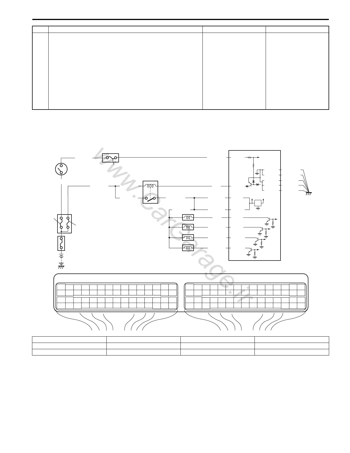
Fuel Injector Circuit Check
S5JB0A1104065
Wiring Diagram
12 Sensor 5 V power source circuit check
1) Disconnect connectors from ECM, TP sensor, MAP
sensor, A/C refrigerant pressure sensor (if equipped with
A/C), electric load current sensor (for J20 engine) and
accelerator pedal position (APP) sensor with ignition
switch turned OFF.
2) Measure each resistance between “C37-14”, “E23-56”,
“E23-54” and “C37-53” terminal of ECM connector and
vehicle body ground.
Is each resistance infinity?
Check internal short
circuit of TP sensor,
MAP sensor, A/C
refrigerant pressure
sensor (if equipped with
A/C), electric load
current sensor (for J20
engine) and/or
accelerator pedal
position (APP) sensor.
“GRY/RED”, “WHT”
and/or “ORN/BLU” wire
is shorted to ground
circuit.
Step Action Yes No
BLK/WHT
BLU/BLK
BLU/BLK
WHT/GRN
BLK/RED BLK/RED
BLK/RED
BLK/YEL
BLU
12V
5V
9
2
8
3
E23-29
E23-1
E23-60
10
E23 C37
34
1819
5671011
1720
47 46495051
2122
52
1625
9
24
14
29
5557 54 53
59
60 58
2
262728
15
30
56 48
32 31343536374042 39 38
44
45 43 41 33
11213
23
834
1819
5671011
1720
47 46495051
2122
52
1625
9
24
14
29
5557 54 53
59
60 58
2
262728
15
30
56 48
32 31343536374042 39 38
44
45 43 41 33
11213
23
8
C37-1
C37-2
C37-16
C37-17
BLU/BLKBLU/BLK
PNK
PNK/GRN
PNK/BLU
PNK/BLK
E23-16
4
5
6
7
1
11
C37-15
C37-29
C37-48
BLK/ORN
C37-58
C37-30
BLK/ORN
BLK/YEL
BLK/YEL
BLK/YEL
I5JB0A110101-01
1. Fuse box No.2 4. No.1 injector 7. No.4 injector 10. “FI” fuse
2. Main relay 5. No.2 injector 8. “IG COIL” fuse 11. “IGN” fuse
3. ECM 6. No.3 injector 9. Ignition switch

 Loading...


