3-8 ENGINE
ENGINE REINSTALLATION
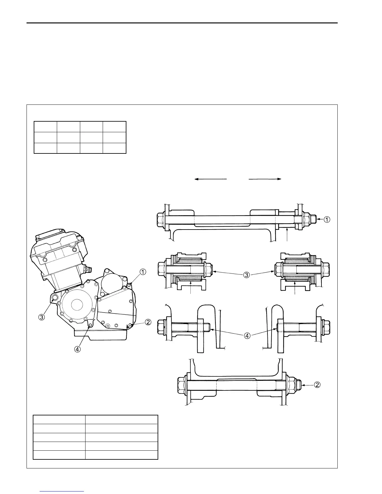
Reinstall the engine in the reverse order of engine removal.
• Insert the two long bolts from left side. Install the brackets, spacer, bolts and nuts properly, as shown in the
following illustration.
NOTE:
The engine mounting nuts are self-locking. Once the nuts have been removed, they are no longer of any use.
Be sure to use new nuts and tighten them to the specified torque.
NOTE:
When reusing the removed engine mounting bolts (
2
and
4
), apply a small quantity of the THREAD LOCK “1342”
to their threads.
#99000-32050: THREAD LOCK “1342”
"
ITEM N
.
m kgf
.
m lb-ft
1, 2 75 7.5 54.0
3, 4 55 5.5 40.0
Left-side
Right-side
Point 1
Spacer A
Point 3
Bushing
Bushing
Point 4
Point 2
LENGTH
Bolt 1 180 mm (7.1 in)
Bolt 2 130 mm (5.1 in)
Bolt 3 55 mm (2.2 in)
Bolt 4 55 mm (2.2 in)
Spacer RH A 27 mm (1.1 in)
Other engine mounting bolts and frame down
tube mounting bolts.
" 32 N
.
m (3.2 kgf
.
m, 23.0 lb-ft)
 Loading...


