Performance Check/ Calibration-Type
453
/ R453
connector'. ,
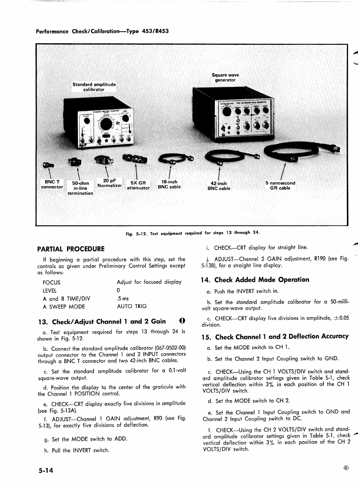
Standard amplitude
calibrator
\
50-ohm
in-line
termination
attenuator
18-inch
BNC
cable
Square wave
generator
I
5 nanosecond
GR
cable
Fig.
5-12.
Test
equipment
required
for
steps
13
through
24.
PARTIAL
PROCEDURE
If
beginning a partial procedure
with
this
step, set the
controls as given under Preliminary Control Settings except
as follows:
FOCUS
LEVEL
A and B
TIME/DIV
A
SWEEP
MODE
Adjust for focused display
0
.5
ms
AUTO
TRIG
13. Check/ Adiust Channel 1 and 2 Gain
0
a. Test equipment required for steps
13
through
24
is
shown
in
Fig.
5-12.
b.
Connect the standard amplitude calibrator
(067-0502-00)
output connector to the Channel l and 2
INPUT
connectors
through a
BNC
T connector and two 42-inch
BNC
cables.
c.
Set the standard amplitude calibrator for a 0.1-volt
square-wave output.
d.
Position the display to the center of the graticule
with
the Channel l
POSITION
control.
e. CHECK-CRT display exactly
five
divisions
in
amplitude
(see
Fig.
5-
l
3A).
f.
ADJUST-Channel l GAIN adjustment,
R90
(see
Fig.
5-13),
for exactly
five
divisions
of
deflection.
g.
Set the
MODE
switch to
ADD.
h.
Pull
the
INVERT
switch.
5-14
i.
CHECK-CRT display for straight
line.
j.
ADJUST-Channel 2 GAIN adjustment, Rl90
(see
Fig.
5-l
3B),
for a straight
line
display.
14.
Check
Added Mode Operation
a.
Push
the
INVERT
switch
in.
b.
Set the standard amplitude calibrator for a
SO-milli-
volt square-wave output.
c.
CHECK-CRT display
five
divisions
in
amplitude,
-+-0.05
division.
15.
Check
Channel 1 and 2 Deflection Accuracy
a. Set the
MODE
switch to
CH
l.
b.
Set the Channel 2 Input Coupling switch to GND.
c.
CHECK-Using the
CH
l
VOLTS/DIV
switch and stand-
ard amplitude calibrator settings given
in
Table 5-l, check
vertical deflection within 3%
in
each position of the
CH
l
VOLTS/DIV
switch.
d.
Set the
MODE
switch to
CH
2.
e. Set the Channel l Input Coupling switch to GND and
Channel 2 Input Coupling switch to
DC.
f.
CHECK-Using the
CH
2
VOLTS/DIV
switch and stand-
ard amplitude calibrator settings given
in
Table 5-l, check
,.,,,.
vertical deflection within 3%
in
each position of the
CH
2
VOL
TS/DIV
switch.
©
 Loading...


