B
SWEEP
GENERATOR
General
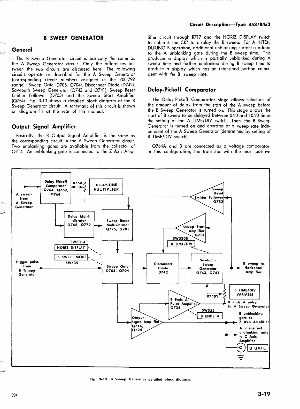
The
B Sweep Generator circuit
is
basically the same as
the A Sweep Generator circuit. Only the differences be-
tween the two circuits are discusssd here.
The
following
circuits operate as described for the A Sweep Generator
(corresponding circuit numbers assigned
in
the 700-799
range): Sweep Gate
(D705,
Q704), Disconnect Diode
(D742),
Sawtooth Sweep Generator (Q743 and Q741), Sweep
Reset
Emitter
Follower
(Q753)
and the Sweep Start Amplifier
(Q754).
Fig.
3-13
shows a detailed block diagram of the B
Sweep Generator circuit. A schematic of
this
circuit
is
shown
on diagram
11
at
the rear of
this
manual.
Output Signal Amplifier
Basically, the B Output Signal Amplifier
is
the same as
the corresponding circuit
in
the A Sweep Generator circuit.
Two
unblanking gates are available
from
the collector of
Q714.
An
unblanking gate
is
connected
to
the Z
Axis
Amp-
A
sweep
from
A
Sweep
Generator
Trigger
pulse
from
B Trigger
Generator
Delay-Pickoff
Comparator
Q764, Q769,
D764
DELAY-TIME
MULTIPLIER
Delay
Multi-
vibrator
Q768,
Q772
SW801A
[H°"oRIZ
DISPLAY
k,
I B
SWEEP
MODE~
.................
SW635
',
Sweep Reset
Multivibrator
Q775,
Q785
Sweep
Gate
D705,
Q704
Circuit
Description-Type
453/R453
lifier
circuit through
R717
and the
HORIZ
DISPLAY
switch
to unblank the
CRT
to display the B sweep.
For
A
INTEN
DURING
B operation, additional unblanking current
is
added
to
the A unblanking gate during the B sweep
time.
This
produces a display which
is
partially unblanked during A
sweep
time
and further unblanked during B sweep
time·
to
produce a display which has an intensified portion coinci-
dent
with
the B sweep
time.
Delay-Pickoff Comparator
The
Delay-Pickoff Comparator stage allows
se·lection
of
the amount of delay
from
the start of the A sweep before
the B Sweep Generator
is
turned on.
This
stage allows the
start of B sweep to be delayed between 0.20 and 10.20
times
the setting of the A
TIME/DIV
switch.
Then,
the B Sweep
Generator
is
turned on and operates
at
a sweep rate inde-
pendent of the A Sweep Generator (determined
by
setting of
B
TIME/DIV
switch).
Q764A and B are connected as a voltage comparator.
In
this
configuration, the transistor
with
the most positive
SW530B
B TIME/DIV I
......
_
Disconnect
Diode
D742
--
Sawtooth
Sweep
Generator
Q743,
Q741
B
sweep
to
Horizontal
Amplifier
~
B TIME/DIV
'-R
7
-
4
-
0
-y-
VARIABLE
>------......~
B
ends
A
pulse
SW555
B
ENDS
A
to A Sweep
Generator
B
unblanking
gate
to
r">-----------__..__...
Z Axis Amplifier
A intensified
unblanking
gate
to Z Axis
Amplifier
~
l,......B_G_A-TE-1
Fig.
3-13.
B
Sweep
Generator
detailed
block
diagram.
3-19
 Loading...


