Operating lnstructions--Type
453/R453
II II II
~
II
II
111111
rrr
Ir.I
r
''I
'!
.,
O
TT
''
---
~~~-
lJJ
JJJ
~
.i
.i.
--·
!Al
A
sweep
display.
--
~
,......,,-
/.
/"
l·I
111
I I
!Bl Delayed
sweep
display.
II II
II
T
'I
......
TT
Pulse to
be
magnified
I
I
!
T
TTTT
TT
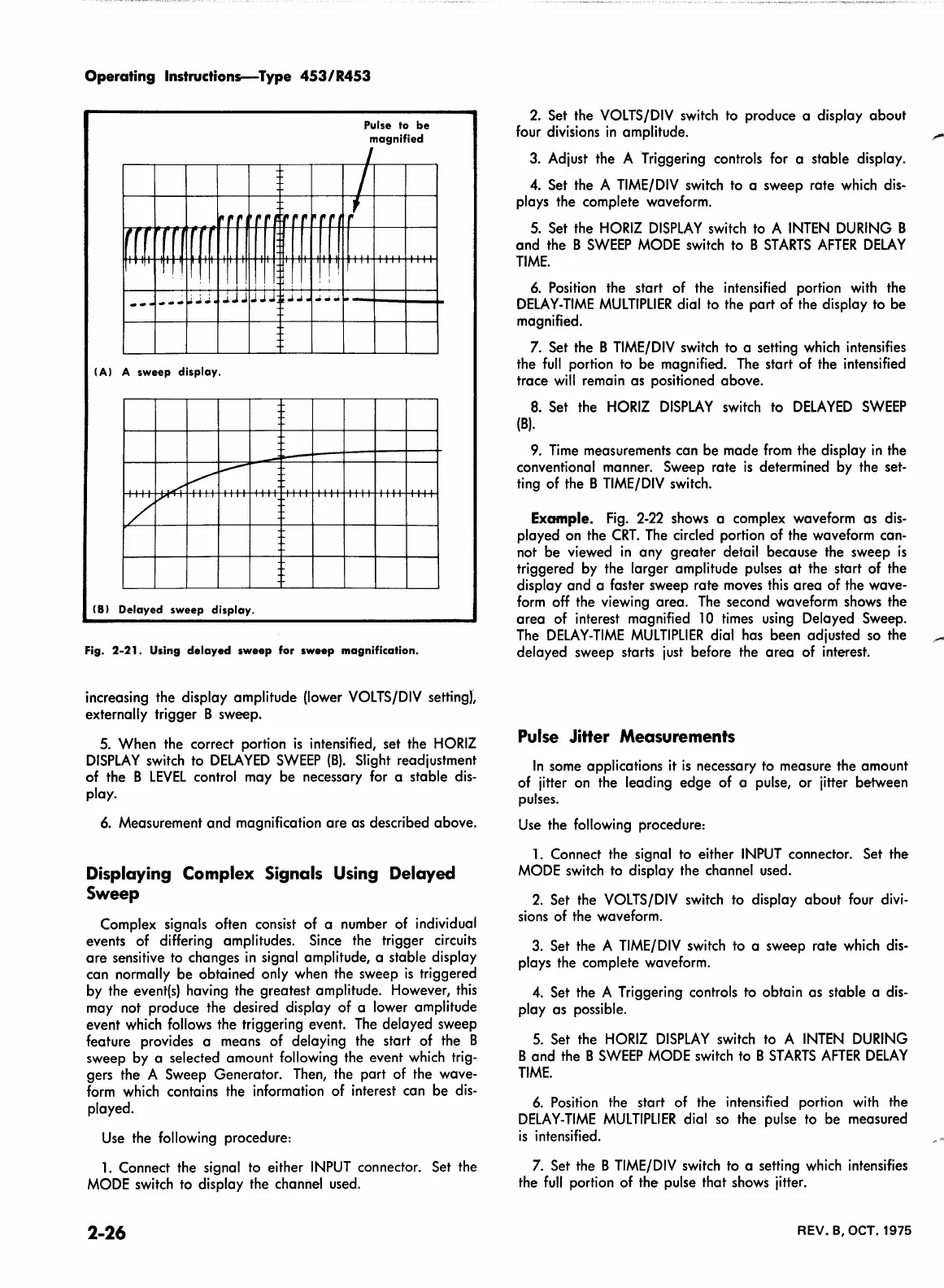
Fig.
2-21.
Using
delayed
sweep
for
sweep
magnification.
increasing the display amplitude (lower
VOLTS/DIV
settingt
externally trigger B sweep.
5.
When the correct portion
is
intensified, set the
HORIZ
DISPLAY
switch
to
DELA
YEO
SWEEP
(B).
Slight readjustment
of the B
LEVEL
control may be necessary
for
a stable
dis-
play.
6.
Measurement and magnification are as described above.
Displaying Complex Signals Using Delayed
Sweep
Complex signals often consist of a number of individual
events of differing amplitudes.
Since
the trigger
circuits
are sensitive
to
changes
in
signal amplitude, a stable display
can normally be obtained only when the sweep
is
triggered
by the
event(s}
having the greatest amplitude. However,
this
may not produce the desired display of a lower amplitude
event
which
follows
the triggering event.
The
delayed sweep
feature provides a means of delaying the start of the B
sweep by a selected amount following the event
which
trig-
gers the A Sweep Generator.
Then,
the part of the wave-
form
which
contains the information of interest can be
dis-
played.
Use
the following procedure:
1.
Connect the signal
to
either
INPUT
connector. Set the
MODE
switch
to
display the channel
used.
2-26
2.
Set the
VOLTS/DIV
switch
to
produce a display about
four
divisions
in
amplitude.
3.
Adjust the A Triggering controls for a stable display.
4.
Set the A
TIME/DIV
switch
to
a sweep rate
which
dis-
plays the complete waveform.
5.
Set the
HORIZ
DISPLAY
switch
to
A
INTEN
DURING
B
and the B
SWEEP
MODE
switch
to
B
ST
ARTS
AFTER
DELAY
TIME.
6.
Position
the start of the intensified portion
with
the
DELAY-TIME
MULTIPLIER
dial
to
the part of the display
to
be
magnified.
7.
Set the B
TIME/DIV
switch
to
a setting
which
intensifies
the
full
portion
to
be magnified.
The
start of the intensified
trace
will
remain as positioned above.
8.
Set the
HORIZ
DISPLAY
switch
to
DELA
YEO
SWEEP
(B).
9.
Time
measurements can be made
from
the display
in
the
conventional manner. Sweep rate
is
determined
by
the set-
ting
of the B
TIME/DIV
switch.
Example.
Fig.
2-22
shows
a complex waveform as
dis-
played
on
the
CRT.
The
circled portion of the waveform can-
not be viewed
in
any greater detail because the sweep
is
triggered
by
the larger amplitude pulses
at
the start of the
display and a faster sweep rate
moves
this
area of the wave-
form
off
the viewing area.
The
second waveform shows the
area of interest magnified
10
times
using
Delayed Sweep.
The
DELAY-TIME
MULTIPLIER
dial has been adjusted
so
the
delayed sweep starts
just
before the area of interest.
Pulse
Jitter Measurements
In
some applications
it
is
necessary to measure the amount
of
jitter
on
the leading edge of a pulse, or jitter between
pulses.
Use
the following procedure:
1.
Connect the signal
to
either
INPUT
connector. Set the
MODE
switch
to
display the channel used.
2.
Set the
VOLTS/DIV
switch
to
display about four
divi-
sions
of the waveform.
3.
Set the A
TIME/DIV
switch
to
a sweep rate
which
dis-
plays the complete waveform.
4.
Set the A Triggering controls to obtain as stable a
dis-
play as possible.
5.
Set the
HORIZ
DISPLAY
switch
to
A
INTEN
DURING
B and the B
SWEEP
MODE
switch
to
B
ST
ARTS
AFTER
DELAY
TIME.
6.
Position
the start of the intensified portion
with
the
DELAY-TIME
MULTIPLIER
dial
so
the pulse
to
be measured
is
intensified.
7.
Set the B
TIME/DIV
switch
to
a setting
which
intensifies
the
full
portion of the pulse that
shows
jitter.
REV. B, OCT. 1975
 Loading...


