Performance
Check/Calibration-Type
453/R453
First
~z··
Ninth-division
vertical line
/_
First-'divisi;n
~
Tenth
ll
ver!ical line
marker
v
~
-
.
.
..
-
.
(A)
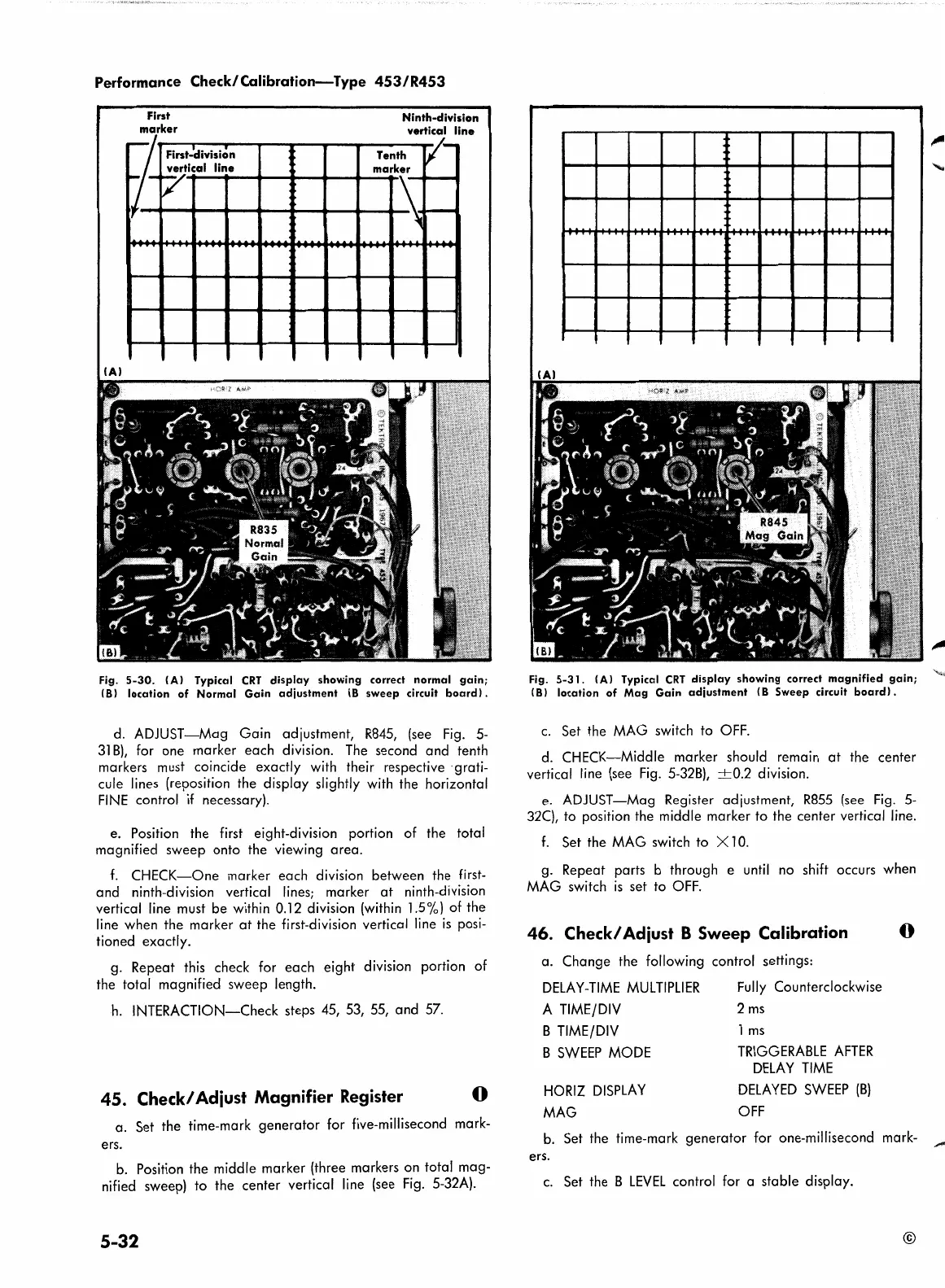
Fig.
5-30.
(A)
Typical
CRT
display
showing
correct
normal
gain;
(8)
location
of
Normal
Gain
adjustment
(8
sweep
circuit
board).
d. ADJUST-Mag Gain adjustment,
R845,
(see
Fig.
5-
31
B),
for one marker each division.
The
second and tenth
markers must coincide exactly with their respective ·grati-
cule lines (reposition the display slightly with the horizontal
FINE
control
if
necessary).
e. Position the first eight-division portion of the total
magnified sweep onto the viewing area.
f.
CHECK-One
marker each division between the
first-
and ninth-division vertical lines; marker
at
ninth-division
vertical line must be within 0.12 division
(within
l.5%) of the
line when the marker
at
the first-division vertical line
is
posi-
tioned exactly.
g. Repeat this check for each eight division portion of
the total magnified sweep length.
h.
INTERACTION-Check steps 45, 53, 55, and
57.
45.
Check/ Adiust Magnifier Register
0
a. Set the time-mark generator for five-millisecond mark-
ers.
b.
Position the middle marker (three markers on total mag-
nified sweep) to the center vertical line (see
Fig.
5-32A).
5-32
.
~
Fig.
5-31.
(A) Typical
CRT
display
showing
correct
magnified
gain;
(8)
location
of
Mag
Gain
adjustment
(8
Sweep
circuit
board).
c.
Set the
MAG
switch to
OFF.
d. CHECK-Middle marker should remain
at
the center
vertical line
(see
Fig.
5-328),
-+-0.2
division.
e.
ADJUST-Mag Register adjustment,
R855
(see
Fig.
5-
32(), to position the middle marker to the center vertical line.
f.
Set the
MAG
switch to X l
0.
g. Repeat parts b through e
until
no
shift occurs when
MAG
switch
is
set to
OFF.
46.
Check/ Adiust B Sweep Calibration 0
a. Change the following control settings:
DELAY-TIME
MULTIPLIER
A
TIME/DIV
B
TIME/DIV
Fully
Counterclockwise
2
ms
1
ms
B
SWEEP
MODE
TRIGGERABLE
AFTER
DELAY
TIME
HORIZ
DISPLAY
DELAYED
SWEEP
(B)
MAG
OFF
b.
Set the time-mark generator for one-millisecond mark-
ers.
c.
Set the B
LEVEL
control for a stable display.
©
 Loading...


