Circuit
Description-Type
453/R453
Q84 and Q94 are connected as a common-emitter phase
inverter (paraphase amplifier)
1
to convert the single-ended
input signal
to
a push-pull output signal. Gain of
this
stage
is
determined
by
the emitter degeneration.
As
the resistance
between the emitters of Q84 and Q94 increases, emitter de-
generation increases also to result
in
less
gain through the
stage.
The
GAIN adjustment,
R90,
varies the resistance be-
tween the
emitter~
to control
the·
overall gain of the Channel
1 Vertical Preamp.
CHANNEL 2
VERTICAL
PREAMP
General
The
Channel 2 Vertical Preamp circuit
is
basically the same
as the Channel 1 Vertical Preamp circuit. Only the
dif-
ferences between the two circuits
are
described here.
Por-
tions of
this
circuit not described
in
the following description
operate
in
the same manner as for the Channel 1 Vertical
Preamp circuit (corresponding circuit numbers assigned
in
the
100-199 range).
Fig.
3-3
shows a detailed block diagram
of the Channel 2 Vertical Preamp circuit. A schematic of
this
circuit
is
shown
in
diagram 3
at
the rear of
this
manual.
Feedback
Amplifier
Basically, the Channel 2 Feedback Amplifier operates as
described for Channel
1.
However, the Channel 2 Vertical
1
Lloyd
P.
Hunter
(ed.
l,
"Handbook
of
Semiconductor Electronics",
second
edition,
McGraw-Hill, New York,
pp.
11-94.
Channel
signal
from
Channel
Vertical
Preamp
Channel
2
signal
from
Channel
2
Vertical
Preamp
Alternate
trace
sync
pulse from
...__~
A
Sweep
Generator
D201-D204
CH
1
Diode
__
Gate
CH
2
D206-D209
Switching
Multivibrator
Q215,
Q225
Preamp circuit does not have a trigger pickoff stage.
To
pro-
vide a load
at
the collector of
Ql
54
similar
to
the load
the Channel 1 Trigger
Pickoff
stage provides
at
the collector
of
QS4,
Cl
59
and
Rl
59
are connected into the circuit.
Paraphase Amplifier
The
basic Channel 2 Paraphase Amplifier configuration
and operation
is
the same as for Channel
1.
However, the
INVERT
switch, SWl
95,
has been
added
in
the Channel 2
circuit.
This
switch allows the displayed signal
from
Chan-
nel
2
to
be inverted.
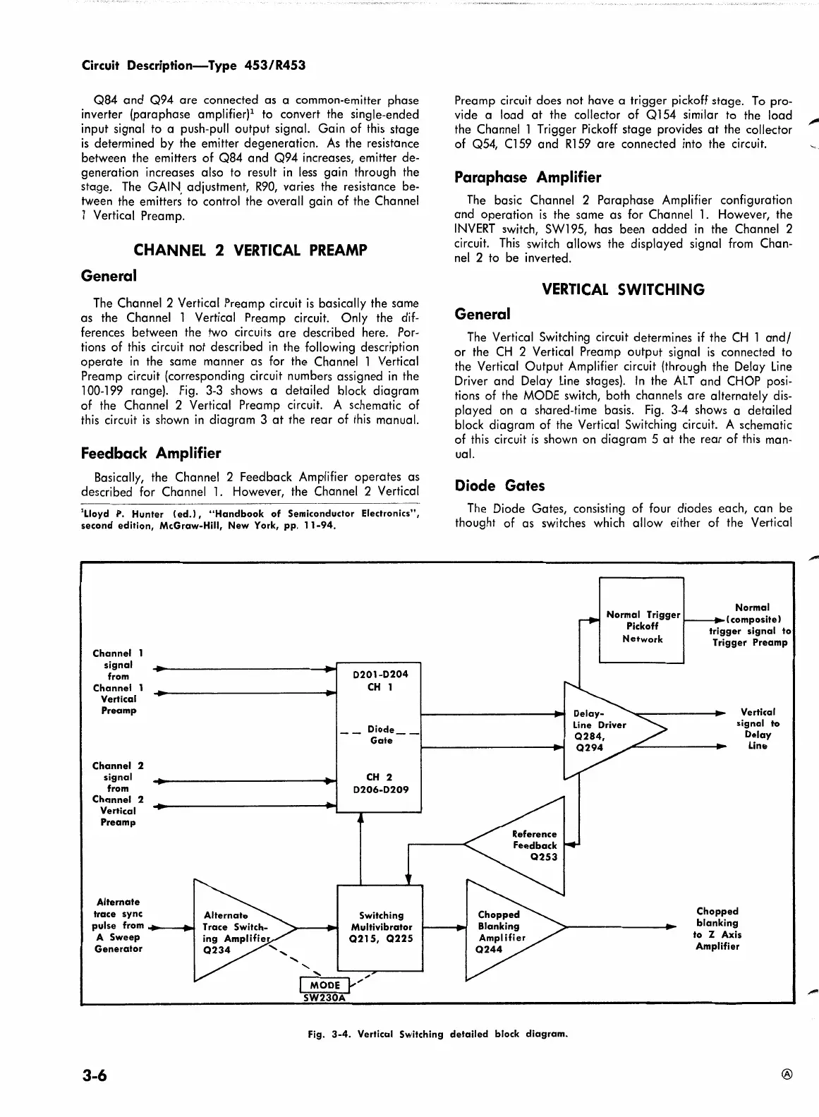
VERTICAL
SWITCHING
General
The
Vertical Switching circuit determines
if
the
CH
1
and/
or the
CH
2 Vertical Preamp output signal
is
connected
to
the Vertical Output Amplifier circuit (through the Delay
Line
Driver and Delay
Line
stages).
In
the
ALT
and
CHOP
posi-
tions of the
MODE
switch, both channels are alternately
dis-
played on a shared-time basis.
Fig.
3-4 shows a detailed
block diagram of the Vertical Switching circuit. A schematic
of
this
circuit
is
shown on diagram 5
at
the rear of
this
man-
ual.
Diode Gates
The
Diode Gates, consisting of four diodes each, can be
thought of as switches which allow either of the Vertical
Normal
Normal Trigger
1---.-(compositel
Pickoff
trigger
signal
to
Network
Trigger
Preamp
Vertical
signal
to
Delay
Line
Chopped
blanking
to Z Axis
Amplifier
Fig.
3-4.
Vertical Switching
detailed
block
diagram.
3-6
®
 Loading...


