Circuit
Description-Type
453/R453
SW635
B
SWEEP
MODE J
SW801A
lHORIZ DISPLAY'
B
trigger
signal
from Trigger
Preamp
SW610
SOURCE
I
I
I
I
INT
I C615
SW615
I COUPLING I
I
I
I
I
I
I
I
LINE
Line
..,.
0
trigger
Pow::~=~
~
I
__
_,,
DC
~~
EXT
TRIG
INPUT
OR
EXT
HORIZ
-+-
1 0
Attenuator
I
I
I
I
I
I
I
I
LEVEL
R660
Trigger
TD
D675
Slope
Comparator
Q654,
Q664
\
\
SW655
I
SLOPE
External
Horizontal
Gain
Network
Trigger
pulse
to
B
Sweep
Generator
External
horizontal
signal to
Horizontal
Amplifier
Fig.
3-12.
B Trigger Generator
detailed
block diagram.
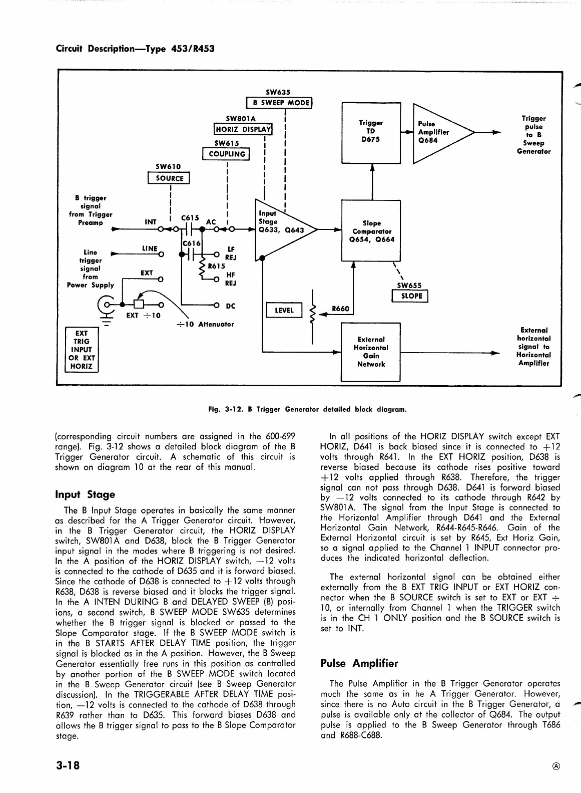
(corresponding circuit numbers are assigned
in
the
600-699
range).
Fig.
3-12 shows a detailed block diagram of the B
Trigger Generator circuit. A schematic of
this
circuit
is
shown on diagram
10
at
the rear of
this
manual.
Input
Stage
The B Input Stage operates
in
basically the same manner
as described for the A Trigger Generator circuit. However,
in
the B Trigger Generator circuit, the
HORIZ
DISPLAY
switch,
SW801
A and
D638,
block the B Trigger Generator
input signal
in
the modes where B triggering
is
not desired.
In
the A position of the
HORIZ
DISPLAY
switch,
-12
volts
is
connected to the cathode of
D635
and
it
is
forward biased.
Since the cathode of
D638
is
connected
to
+
12
volts through
R638,
D638
is
reverse biased and
it
blocks the trigger signal.
In
the A
INTEN
DURING
B and
DELAYED
SWEEP
(B)
posi-
ions, a second switch, B
SWEEP
MODE
SW635 determines
whether the B trigger signal
is
blocked or passed
to
the
Slope Comparator stage.
If
the B
SWEEP
MODE
switch
is
in
the B
STARTS
AFTER
DELAY
TIME
position, the trigger
signal
is
blocked as
in
the A position. However, the B Sweep
Generator essentially free
runs
in
this
position as controlled
by another portion of the B
SWEEP
MODE
switch located
in
the B Sweep Generator circuit
(see
B Sweep Generator
discussion).
In
the
TRIGGERABLE
AFTER
DELAY
TIME
posi-
tion,
-12
volts
is
connected to the cathode of
D638
through
R639
rather than
to
D635.
This
forward biases
D638
and
allows the B trigger signal
to
pass
to
the B Slope Comparator
stage.
3-18
In
all positions of the
HORIZ
DISPLAY
switch except
EXT
HORIZ,
D641
is
back biased since
it
is
connected to +
12
volts through
R641.
In
the
EXT
HORIZ
position,
D638
is
reverse biased because
its
cathode
rises
positive toward
+
12
volts applied through
R638.
Therefore, the trigger
signal can not pass through
D638.
D641
is
forward biased
by
-12
volts connected to
its
cathode through
R642
by
SW801
A.
The
signal
from
the Input Stage
is
connected
to
the Horizontal Amplifier through
D641
and the External
Horizontal Gain Network,
R644-R645-R646.
Gain of the
External Horizontal circuit
is
set
by
R645,
Ext
Horiz Gain,
so
a signal applied to the Channel 1
INPUT
connector pro-
duces the indicated horizontal deflection.
The
external horizontal signal can be obtained either
externally
from
the B
EXT
TRIG
INPUT
or
EXT
HORIZ
con-
nector when the B
SOURCE
switch
is
set
to
EXT
or
EXT
-;-
10,
or internally
from
Channel 1 when the
TRIGGER
switch
is
in
the
CH
1
ONLY
position and the B
SOURCE
switch
is
set
to
INT.
Pulse Amplifier
The
Pulse
Amplifier
in
the B Trigger Generator operates
much
the same as
in
he
A Trigger Generator. However,
since there
is
no
Auto circuit
in
the B Trigger Generator, a
""""
pulse
is
available only
at
the collector of Q684.
The
output
pulse
is
applied
to
the B Sweep Generator through
T686
and
R688-C688.
®
 Loading...


