......
Circuit
Description-Type
453/R453
+
12
v
+75V
r----1
SLOPE
l-----1
:
SW455
I
I
I
I
R467
C467
'---i
C473
R473
R468
0475
C456
I
C466
I
R469
L469
R459
Q473
R471
*
~
0456 0466
Current
path
*
Reverse-biased
diode
----1>1
-12V
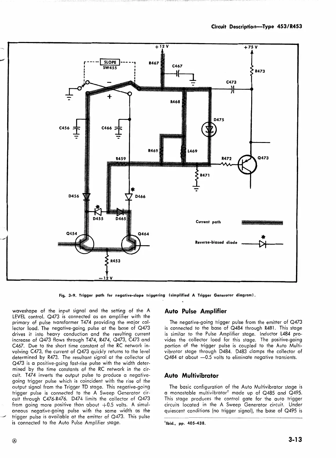
Fig.
3-9.
Trigger
path
for
negative-slope
triggering
(simplified A Trigger
Generator
diagram).
waveshape
of
the input signal and the setting
of
the A
LEVEL
control. Q473
is
connected
as
an
amplifier
with the
primary
of
pulse transformer
T474
providing the major col-
lector load.
The
negative-going pulse
at
the base
of
Q473
drives
it
into heavy conduction and the resulting current
increase
of
Q473 flows through
T474,
R474,
Q473, C473 and
C467. Due to the short time constant
of
the
RC
network in-
volving C473, the current
of
Q473 quickly returns to the level
determined by
R473.
The
resultant signal
at
the collector
of
Q473
is
a positive-going fast-rise pulse with the width deter-
mined
by
the time constants
of
the
RC
network in the cir-
cuit.
T474
inverts the output pulse to produce a negative-
going trigger pulse which
is
coincident with the
rise
of
the
output signal from the Trigger
TD
stage.
This
negative-going
trigger pulse
is
connected to the A Sweep Generator cir-
cuit through
C476-R476.
D474 limits the collector
of
Q473
from going more positive than
about
+0.5
volts. A simul-
aneous negative-going pulse with the same width
as
the
trigger pulse
is
available
at
the emitter
of
Q473.
This
pulse
is
connected to the Auto
Pulse
Amplifier
stage.
@
Auto
Pulse Amplifier
The
negative-going trigger pulse from the emitter
of
Q473
is
connected to the base
of
Q484 through
R481.
This
stage
is
similar to the
Pulse
Amplifier stage. Inductor
L484
pro-
vides the collector load for this stage.
The
positive-going
portion
of
the trigger pulse
is
coupled to the Auto Multi-
vibrator
stage through D484. D483 clamps the collector
of
Q484
at
about
-0.5
volts to eliminate negative transients.
Auto
Multivibrator
The
basic configuration
of
the Auto
Multivibrator
stage
is
a monostable multivibrator
7
made up
of
Q485 and Q495.
This
stage produces the control gate for the auto trigger
circuits located
in
the A Sweep Generator circuit. Under
quiescent conditions
(no
trigger signal), the base
of
Q495
is
7
1bid.,
pp.
405-438.
3-13
 Loading...


