.
. . .
\
\
IA)
'
181
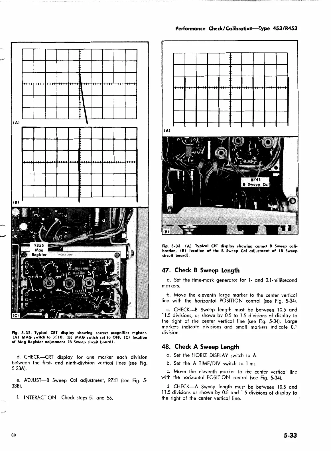
Fig.
5-32.
Typical
CRT
display
showing
correct
magnifier
register.
IAI MAG switch
to
XlO,
181
MAG switch
set
to
OFF,
!Cl
location
of
Mag
Register
adjustment
(8
Sweep
circuit
board).
d.
CHECK-CRT display for one marker each division
between the
first-
and ninth-division vertical
lines
(see
Fig.
5-33A).
e. ADJUST-B Sweep Cal adjustment,
R741
(see
Fig.
5-
338).
f.
INTERACTION-Check steps
51
and
56.
©
Performance Check/Calibration-Type
453/R453
IA)
Fig.
5-33.
IAI Typical
CRT
display
showing
correct 8
Sweep
cali-
bration,
(81
location
of
the
8
Sweep
Cal
adjustment
of
(8
Sweep
circuit
board).
47.
Check
B Sweep
Length
a. Set the time-mark generator for
1-
and 0.1-millisecond
markers.
b. Move the eleventh large marker to the center vertical
line
with
the horizontal
POSITION
control
(see
Fig.
5-34).
c.
CHECK-B Sweep length
must
be between
10.5
and
11.5
divisions, as shown
by
0.5
to
1.5
divisions of display to
the right of the center vertical
line
(see
Fig.
5-34).
Large
markers indicate divisions and small markers indicate
0.1
division.
48.
Check
A Sweep
Length
a.
Set the
HORIZ
DISPLAY
switch to
A.
b.
Set the A
TIME/
DIV
switch
to
1
ms.
c.
Move the eleventh marker to the center vertical
line
with
the horizontal
POSITION
control
(see
Fig.
5-34).
d.
CHECK-A Sweep length
must
be between
10.5
and
11.5
divisions as shown
by
0.5
and
1.5
divisions of display to
the right of the center vertical
line.
5-33
 Loading...


