Maintenance--Type
453/R453
4.
To
remove the
complete
wiring assembly from the high-
voltage
compartment,
unsolder the post-deflection
anode
lead
(heavily insulated
lead
at
side
of
compartment). The
other
leads
are
long
enough
to
allow
the assembly to
be
lifted
out
of
the
compartment
to
reach
the parts
on
the
under
side.
5. To
replace
the
high-voltage
compartment,
reverse the
order
of
removal.
NOTE
All
solder
joints
in
the
high-voltage
compartment
should
have
smooth
surfaces.
Any
protrusions
may
cause
high-voltage
arcing
at
high
altitudes.
Recalibration After Repair
After
any
electrical
component
has
been
replaced,
the
calibration
of
that
particular
circuit should
be
checked,
as
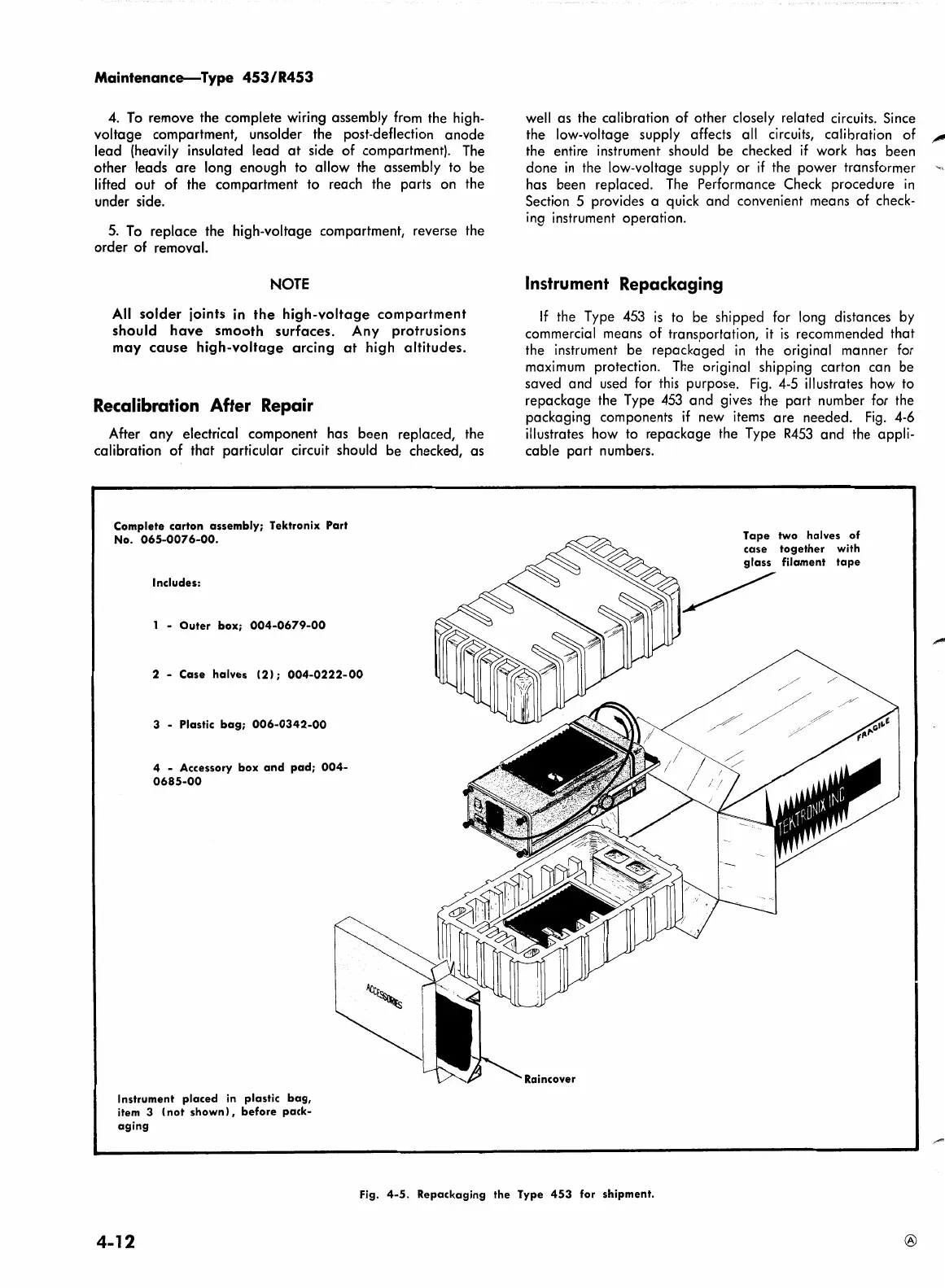
Complete
carton
assembly;
Tektronix
Part
No.
065-0076-00.
Includes:
1 -
Outer
box;
004-0679-00
2 -
Case
halves
(2);
004-0222-00
3 - Plastic
bag;
006-0342-00
4 - Accessory
box
and
pad;
004-
0685-00
Instrument
placed
in plastic
bag,
item 3
(not
shown)
,
before
pack-
aging
well
as
the calibration
of
other
closely
related
circuits. Since
the low-voltage supply affects all circuits, calibration
of
"""'
the entire instrument should
be
checked
if
work has
been
done
in
the low-voltage supply
or
if
the
power
transformer
has
been
replaced.
The Performance Check
procedure
in
Section 5 provides a quick
and
convenient means
of
check-
ing instrument
operation.
Instrument Repackaging
If
the Type 453
is
to
be
shipped
for long distances by
commercial means
of
transportation, it
is
recommended
that
the instrument
be
repackaged
in
the original
manner
for
maximum protection. The original shipping
carton
can
be
saved
and
used for this purpose. Fig. 4-5 illustrates how to
repackage
the Type 453
and
gives the
part
number for the
packag~ng
components
if
new
items
are
needed.
Fig. 4-6
illustrates how
to
repackage
the Type
R453
and
the appli-
cable
part
numbers.
Tape
two
halves
of
case
together
with
glass
filament
tape
~
Fig.
4-5.
Repackaging
the
Type
453
for shipment.
4-12
®
 Loading...


