(Al
This
portion
of
display
cannot
be
viewed
ade-
quately
because
A
sweep
is
triggered
on
larger
amplitude
signals
at
start
of
display.
-
...II\.
I/.\
./.
TTl
l
Tlo
-.
II
I/'
vi
v
"'\V
v
.k.J
I
I
(Bl
Area
of
interest
displayed
by
delaying
B
sweep
( B
ST
ARTS
AFTER
DELAY
TIME
mode
I .
Fig.
2-22.
Displaying a complex
signal
using
delayed
sweep.
8. Set
the
HORIZ DISPLAY switch
to
DELAYED
SWEEP (B).
9. Pulse jitter
is
shown by horizontal movement
of
the
pulse (take into account inherent jitter
of
Delayed Sweep).
Measure the
amount
of horizontal movement.
Be
sure both
VARIABLE controls are set
to
CAL.
10. Multiply the distance measured
in
step 9 by the
B Tl ME/DIV switch setting
to
obtain pulse jitter
in
time.
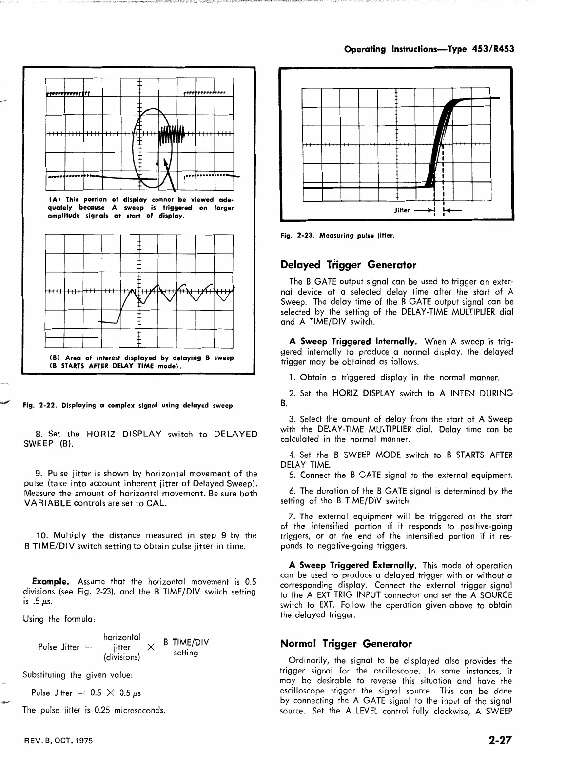
Example.
Assume
that the horizontal movement
is
0.5
divisions (see
Fig.
2-23),
and the B
TIME/DIV
switch setting
is
.5
µs.
Using
the formula:
Pulse
Jitter =
horizontal X B
TIME/DIV
jitter
(divisions)
setting
Substituting the given value:
Pulse
Jitter =
0.5
X
0.5
µs
The
pulse jitter
is
0.25
microseconds.
REV.
8,
OCT.
1975
Operating
Instructions-Type
453/R453
~
-
I
Jitter~
Fig.
2-23.
Measuring
pulse
jitter.
Delayed- Trigger
Generator
,
...
I
1
I
I
I
I
;
~
i
!
I
'-+-
I
The
B
GATE
output signal can be used to trigger an exter-
nal device
at
a selected delay time after the start of A
Sweep.
The
delay time of the B
GATE
output signal can be
selected by the setting of the
DELAY-TIME
MULTIPLIER
dial
and A
TIME/DIV
switch.
A
Sweep
Triggered Internally. When A sweep
is
trig-
gered internally to produce a normal display. the delayed
trigger may be obtained as follows.
1.
Obtain a triggered display
in
the normal manner.
2.
Set the
HORIZ
DISPLAY
switch to A
INTEN
DURING
B.
3.
Select the amount of delay
from
the start of A Sweep
with
the
DELAY-TIME
MULTIPLIER
dial. Delay time can be
calculated
in
the normal manner.
4.
Set the B
SWEEP
MODE
switch to B
ST
ARTS
AFTER
DELAY
TIME.
5.
Connect the B
GATE
signal to the external equipment.
6.
The
duration of the B
GATE
signal
is
determined by the
setting of the
B
TIME/DIV
switch.
7.
The
external equipment
will
be triggered
at
the start
of the intensified portion
if
it
responds to positive-going
triggers, or
at
the end of the intensified portion
if
it
res-
ponds to negative-going triggers.
A
Sweep
Triggered Externally.
This
mode of operation
can be used to produce a delayed trigger
with
or without a
corresponding display. Connect the external trigger signal
to the A
EXT
TRIG
INPUT
connector and set the A
SOURCE
switch to
EXT.
Follow the operation given above to obtain
the delayed trigger.
Normal
Trigger Generator
Ordinarily, the signal
to
be displayed also provides the
trigger signal for the oscilloscope.
In
some instances,
it
may be desirable
to
reverse
this
situation and have the
oscilloscope trigger the signal source.
This
can be done
by connecting the A
GATE
signal to the input of the signal
source. Set the A
LEVEL
control
fully
clockwise, A
SWEEP
2-27
 Loading...


