(A)
Markers
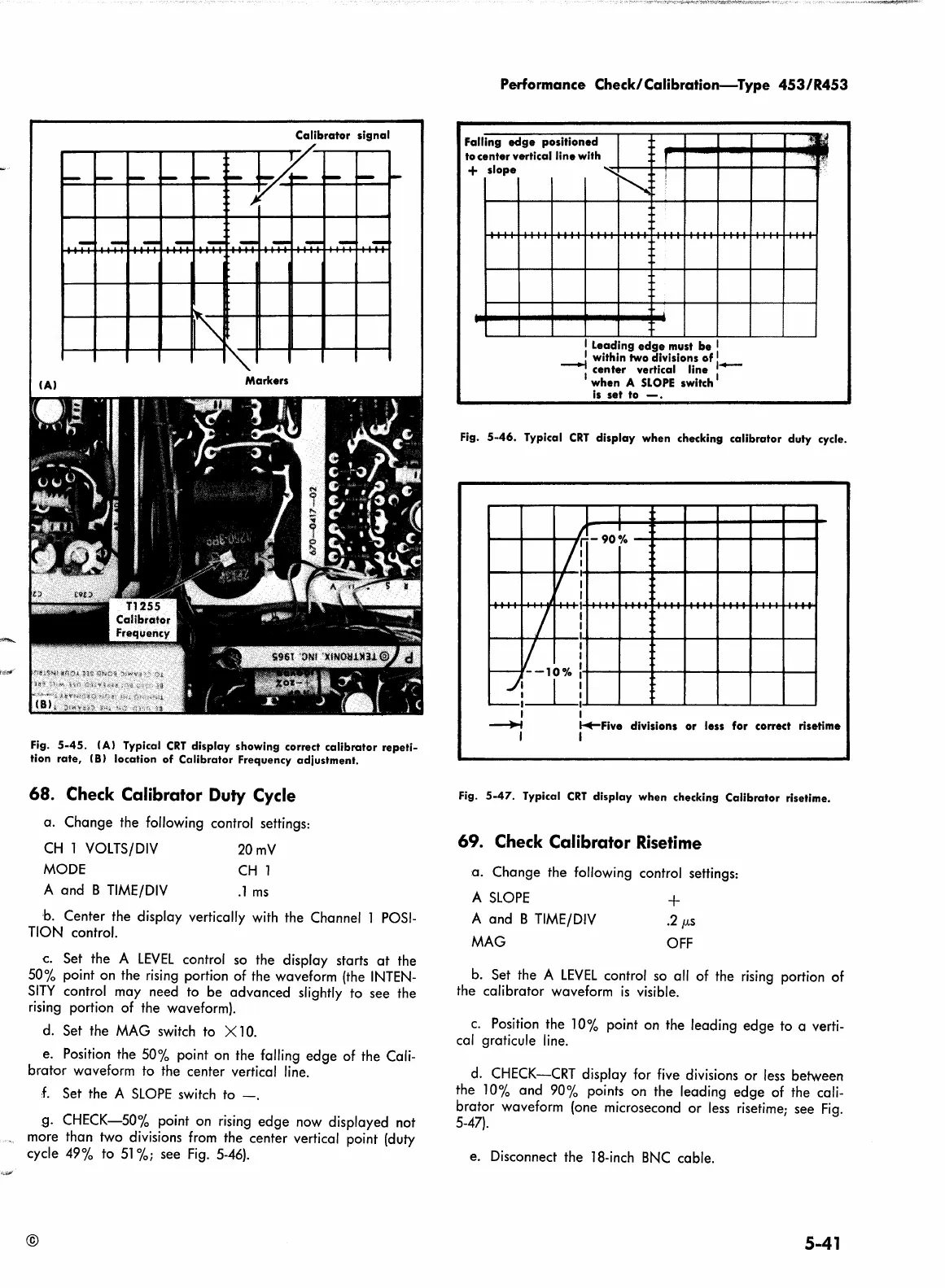
Fig.
5-45.
(A) Typical
CRT
display showing correct
calibrator
repeti-
tion
rate,
(8)
location
of
Calibrator Frequency adjustment.
68. Check Calibrator Duty Cycle
a. Change the following control settings:
CH
1
VOLTS/DIV
MODE
A and B
TIME/DIV
20mV
CH
1
.1
ms
b. Center the display vertically
with
the Channel 1
POSI-
TION
control.
c.
Set the A
LEVEL
control so the display starts
at
the
50% point on the
rising
portion of the waveform
(the
INTEN-
SITY
control may need to be advanced slightly to see the
rising
portion of the waveform).
d.
Set the
MAG
switch
to X
10.
e.
Position the 50% point
on
the falling edge
of
the Cali-
brator waveform to the center vertical
line.
.f.
Set the A
SLOPE
switch to
-.
;g.
CHECK-50% point
on
rising
edge
now
displayed not
more than two divisions
from
the center vertical point (duty
cycle
49%
to
51
%;
see
Fig.
5-46).
©
Performance Check/
Calibration-Type
453/R453
Fa
to
+
lling
edge
positioned
center
vertical line with
~
f
slope
.
~~
!
.
i
I Leading
edge
must
be
I
-J
within two divisions
of
:
1
center
vertical line
,-
when
A
SLOPE
switch
is
set
to
-.
'
D'l
~.
~
Fig.
5-46.
Typical
CRT
display when
checking calibrator duty cycle.
If
-.
;r.-90%
I/
~
·'
.
.
•,
T
/
.
i---
~-10%
~:_l_,
I I
-+f
I
~Five
divisions
or
less for correct risetime
I
Fig.
5-47.
Typical
CRT
display
when
checking Calibrator risetime.
69. Check Calibrator Risetime
a. Change the following control settings:
A
SLOPE
A and B
TIME/DIV
MAG
+
.2
µs
OFF
b.
Set the A
LEVEL
control
so
all
of
the
rising
portion of
the calibrator waveform
is
visible.
c.
Position the 10% point on the leading edge to a verti-
cal graticule
line.
d.
CHECK-CRT display for
five
divisions or
less
between
the
10%
and 90% points on the leading edge of the cali-
brator waveform (one microsecond or
less
risetime; see
Fig.
5-47).
e. Disconnect the
18-inch
BNC
cable.
5-41
 Loading...


