Performance
Check/Calibration-Type
453/R453
Intensified
-
Intensified
portion
portion
v
J
\
I\
I
....
\
....
11
1
1111
1111 1111
11
''
....
,...
....
(A)
18)
I
~
~.
\
1
'''
''''
'''
'' ''
" " '
..
\
-
,,
ICJ
ID)
'
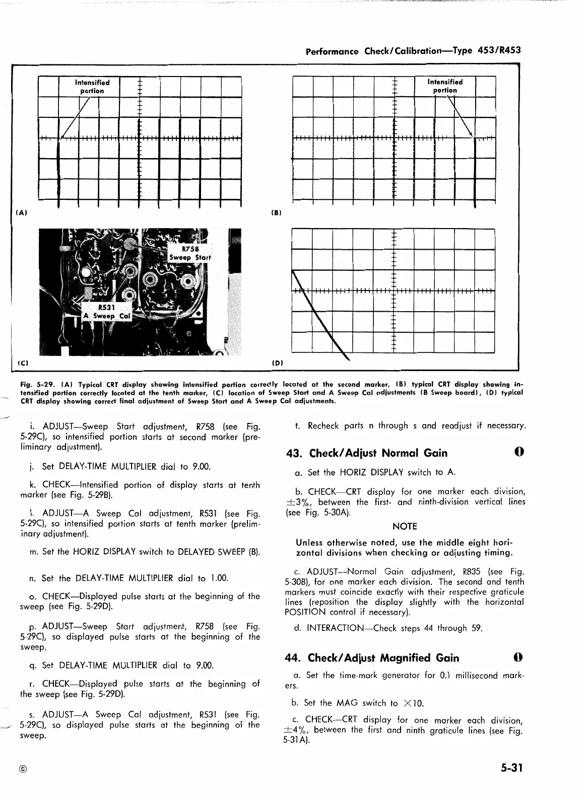
Fig.
5-29.
IA) Typical
CRT
display
showing
intensified
portion
correctly
located
at
the
second
marker,
(8)
typical
CRT
display
showing in-
tensified
portion
correctly
located
at
the
tenth
marker, (
C)
location
of
Sweep
Start
and
A
Sweep
Cal
adjustments
I B
Sweep
board),
<D)
typical
CRT
display
showing
correct final
adjustment
of
Sweep
Start
and
A
Sweep
Cal
adjustments.
i.
ADJUST-Sweep Start adjustment,
R758
(see
Fig.
5-29(), so intensified portion starts
at
second marker (pre-
liminary adjustment).
j.
Set
DELAY-TIME
MULTIPLIER
dial to 9.00.
k.
CHECK-Intensified portion of display starts
at
tenth
marker (see
Fig.
5-298).
I.
ADJUST-A Sweep Cal adjustment,
R53l
(see
Fig.
5-29(}, so intensified portion starts
at
tenth marker (prelim-
inary adjustment).
m.
Set the
HORIZ
DISPLAY
switch to
DELAYED
SWEEP
(8).
n.
Set the
DELAY-TIME
MULTIPLIER
dial to l.00.
o. CHECK-Displayed pulse starts
at
the beginning of the
sweep (see
Fig.
5-29D).
p.
ADJUST-Sweep Start adjustment,
R758
(see
Fig.
5-29(}, so displayed pulse starts
at
the beginning of the
sweep.
q. Set
DELAY-TIME
MULTIPLIER
dial to 9.00.
r.
CHECK-Displayed pulse starts
at
the beginning of
the sweep (see
Fig.
5-29D).
s.
ADJUST-A Sweep Cal adjustment,
RS3l
(see
Fig.
5-29(}, so displayed pulse starts
at
the beginning of the
sweep.
©
t.
Recheck parts n through s and readjust
if
necessary.
43. Check/ Adiust Normal Gain
:a.
Set the
HORIZ
DISPLAY
switch to
A.
0
b.
CHECK-CRT display for one marker each division,
+3%,
between the
first-
and ninth-division vertical lines
(see
Fig.
5-30A).
NOTE
Unless
otherwise
noted,
use
the
middle
eight
hori-
zontal
divisions
when
checking
or
adjusting timing.
c.
ADJUST-Normal Gain adjustment,
R835
(see
Fig.
5-308), for one marker each division.
The
second and tenth
markers
must
coincide exactly with their respective graticule
lines (reposition the display slightly
with
the horizontal
POSITION control
if
necessary).
d.
INTERACTION-Check steps
44
through
59.
44. Check/ Adiust Magnified Gain 0
a. Set the time-mark generator for
0.1
millisecond mark-
ers.
b.
Set the
MAG
switch to X l
0.
c.
CHECK-CRT display for one marker each division,
±4
°/o,
between the first and ninth graticule
lines
(see
Fig.
5-31A).
5-31
 Loading...


