Performance
Check/Calibration-Type
453/R453
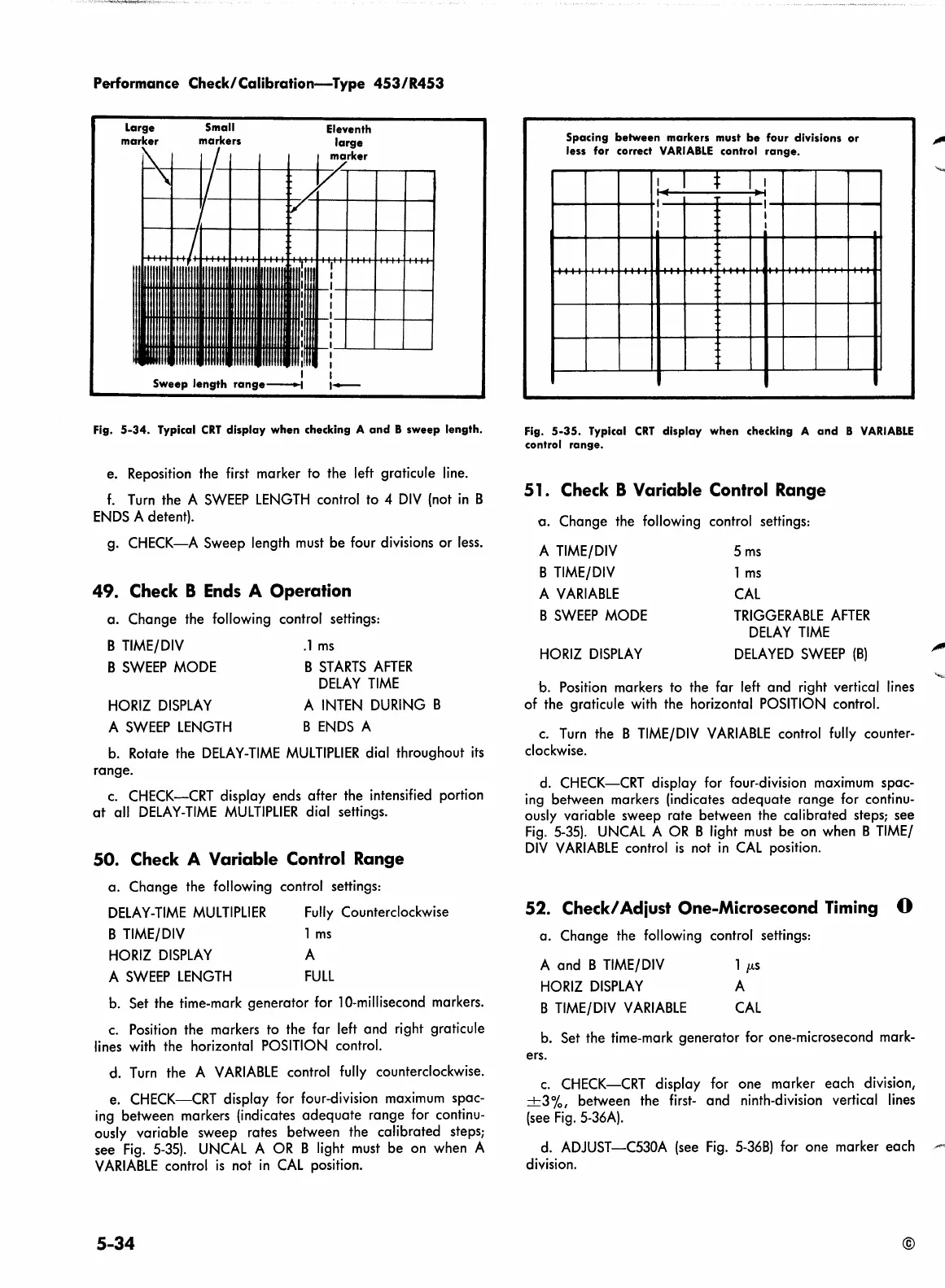
Large
marker
Small
markers
Eleventh
large
t---i-~+i--+~~-4~'~k-er-+-__.,___
Fig.
5-34.
Typical
CRT
display when checking A
and
B
sweep
length.
e.
Reposition the first marker to the left graticule line.
f. Turn the A
SWEEP
LENGTH control to 4 DIV (not in B
ENDS
A detent).
g.
CHECK-A
Sweep length
must
be four divisions
or
less.
49.
Check B Ends A Operation
a. Change the following control settings:
B TIME/DIV
B
SWEEP
MODE
HORIZ
DISPLAY
A
SWEEP
LENGTH
.1
ms
B
ST
ARTS
AFTER
DELAY
TIME
A INTEN DURING B
B
ENDS
A
b.
Rotate the
DELAY-TIME
MULTIPLIER
dial throughout its
range.
c.
CHECK-CRT display
ends
after the intensified portion
at
all
DELAY-TIME
MULTIPLIER
dial settings.
50. Check A Variable Control Range
a. Change the following control settings:
DELAY-TIME
MU
L
Tl
PLIER
B TIME/DIV
HORIZ
DISPLAY
A
SWEEP
LENGTH
Fully Counterclockwise
1
ms
A
FULL
b.
Set
the time-mark generator
for
10-millisecond markers.
c.
Position the markers to the far left and right graticule
lines with the horizontal POSITION control.
d. Turn the A
VARIABLE
control fully counterclockwise.
e.
CHECK-CRT display
for
four-division maximum spac-
ing between markers (indicates adequate range for continu-
ously variable sweep rates between the calibrated
steps;
see
Fig.
5-35).
UNCAL A
OR
B light
must
be
on
when A
VARIABLE
control
is
not in CAL position.
5-34
Spacing
between
markers must
be
four divisions
or
less for correct
VARIABLE
control
range.
I
I
lllf
Ill
I
I
I
I
I
I
I
. .
.
Fig.
5-35.
Typical
CRT
display when checking A
and
B
VARIABLE
control range.
51
. Check B Variable Control Range
a. Change the following control settings:
A TIME/DIV
5
ms
B TIME/DIV
1
ms
A
VARIABLE
CAL
B
SWEEP
MODE
TRIGGERABLE
AFTER
DELAY
TIME
HORIZ
DISPLAY
DELAYED
SWEEP
(B)
b. Position markers to the far left and right vertical lines
of
the graticule with the horizontal POSITION control.
c.
Turn
the B TIME/DIV
VARIABLE
control fully counter-
clockwise.
d. CHECK-CRT display
for
four-division maximum spac-
ing between markers (indicates adequate range for continu-
ously variable sweep rate between the calibrated
steps;
see
Fig.
5-35).
UNCAL A
OR
B light
must
be
on
when B TIME/
DIV
VARIABLE
control
is
not in
CAL
position.
52. Check/ Adiust One-Microsecond Timing
a.
Change the following control settings:
A and B
TIME/DIV 1
µ.s
HORIZ
DISPLAY
A
B TIME/DIV
VARIABLE
CAL
0
b.
Set
the time-mark generator
for
one-microsecond mark-
ers.
c.
CHECK-CRT display for one marker each division,
+3%,
between the first- and ninth-division vertical lines
(see
Fig.
5-36A).
d. ADJUST-C530A
(see
Fig.
5-36B)
for
one marker each
division.
©
"""
'
 Loading...


