32.
Check
A and B Internal Triggering
Operation
a. Set the constant-amplitude generator for a 0.2-division
display
at
10
megahertz
(use
AUTO
TRIG
position,
if
nec-
essary,
to
obtain display).
b.
Set the A and B
TIME/DIV
switch to
.1
µs.
c.
CHECK-Stable
CRT
display
(see
Fig.
5-22A)
can be
obtained
with
the A
COUPLING
switch set to
AC,
LF
REJ
and
DC
(A
LEVEL
control may be adjusted as necessary to
obtain stable display).
The
A
SWEEP
TRIG'D
light
must
be
on when the display
is
stable.
d.
Set the constant-amplitude generator for a one-division
display
at
50
megahertz.
e.
Set the
MAG
switch to X
10.
f.
CHECK-Stable
CRT
display
(see
Fig.
5-22B)
can be
obtained
with
the A
COUPLING
switch set
to
AC,
LF
REJ
and
DC
(A
LEVEL
and
HF
STAB
controls may be adjusted as
necessary to obtain stable display). Display jitter should not
exceed
0.1
division (one nanosecond).
g. Change the following control settings:
A
LEVEL
HORIZ
DISPLAY
Set for stable A display
DELAYED
SWEEP
(B)
h.
Set the constant-amplitude generator for one-division
display
at
50
megahertz
(as
set
in
part d above).
i.
CHECK-Stable
CRT
display
(see
Fig.
5-22B)
can be
obtained
with
the B
COUPLING
switch set to
AC,
LF
REJ
and
DC
(B
LEVEL
control may be adjusted as necessary to
obtain stable display).
j.
Set the constant-amplitude generator for a 0.2-division
display
at
10
megahertz.
k.
Set the
MAG
switch
to
OFF.
I.
CHECK-Stable
CRT
display
(see
Fig.
5-22A)
can be
obtained
with
the B
COUPLING
switch set to
AC,
LF
REJ
and
DC
(B
LEVEL
control may be adjusted as necessary to
obtain a stable display).
33.
Check
A and B External Triggering
Operation
a. Change the following control settings:
SOURCE
(A
and
B)
HORIZ
DISPLAY
MAG
EXT
A
OFF
b.
Set the constant-amplitude generator for a one-division
display
(50
millivolts)
at
10
megahertz.
c.
CHECK-Stable
CRT
display
(see
Fig.
5-23A)
can be
obtained
with
the A
COUPLING
switch
set to
AC,
LF
REJ
and
DC
(A
LEVEL
control may be adjusted as necessary
to
obtain stable display).
©
Performance Check/Calibration-Type
453/R453
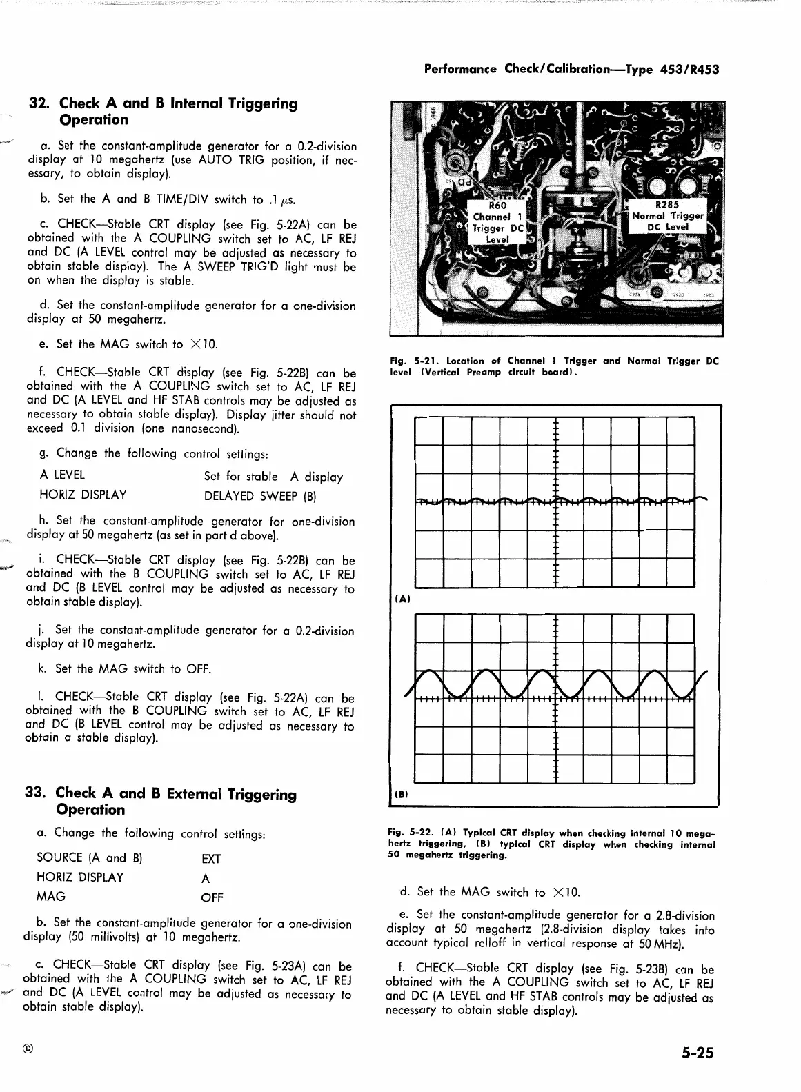
Fig.
5-21.
Location
of
Channel
1 Trigger
and
Normal Trigger
DC
level !Vertical
Preamp
circuit
board).
·~
·~
!Al
v
v'
ir'
v~
~.)
v "
~.)
/'
~
,J
I
r\..
~
~.)
.
lBl
Fig.
5-22.
(Al
Typical
CRT
display
when
checking
internal
10
mega-
hertz
triggering,
!Bl typical
CRT
display
when
checking
internal
50
megahertz
triggering.
d.
Set the
MAG
switch to X
10.
e. Set the constant-amplitude generator for a 2.8-division
display
at
50
megahertz (2.8-division display takes into
account typical rolloff
in
vertical response
at
50
MHz).
f.
CHECK-Stable
CRT
display
(see
Fig.
5-23B)
can be
obtained
with
the A
COUPLING
switch set to
AC,
LF
REJ
and
DC
(A
LEVEL
and
HF
STAB
controls may be adjusted as
necessary to obtain stable display).
5-25
 Loading...


