Performance
Check/Calibration-Type
453/R453
IA>
(8)
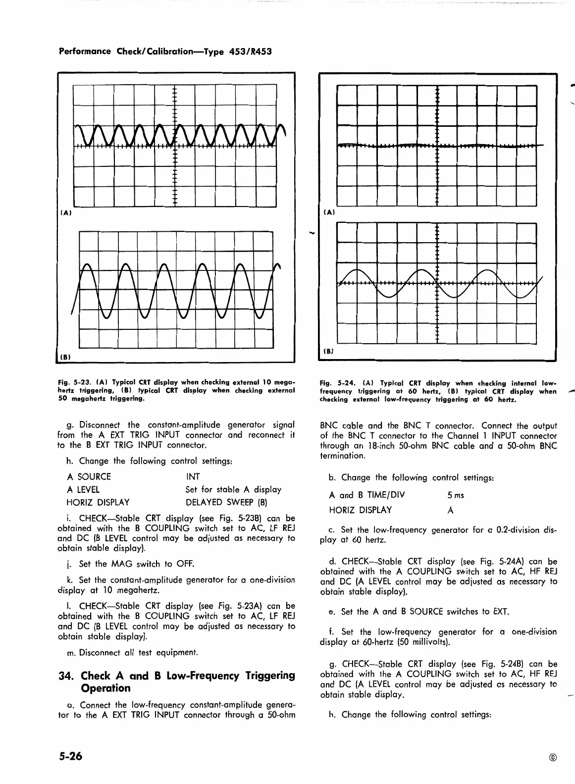
Fig.
5-23.
(A) Typical
CRT
display
when
checking
external
10
mega-
hertz
triggering,
(8)
typical
CRT
display
when
checking
external
50
megahertz
triggering.
.
g.
Disconnect the constant-amplitude generator signal
from
the A
EXT
TRIG
INPUT
connector and reconnect
it
to the 8
EXT
TRIG
INPUT
connector.
h.
Change the following control settings:
A
SOURCE
A
LEVEL
HORIZ
DISPLAY
INT
Set for stable A display
DELAYED
SWEEP
(8)
i.
CHECK-Stable
CRT
display
(see
Fig.
5-238)
can be
obtained
with
the 8
COUPLING
switch
set to
AC,
LF
REJ
and
DC
(8
LEVEL
control may be adjusted as necessary to
obtain stable display).
j.
Set the
MAG
switch to
OFF.
k.
Set the constant-amplitude generator for a one-division
display
at
l 0 megahertz.
I.
CHECK-Stable
CRT
display
(see
Fig.
5-23A)
can be
obtained
with
the 8
COUPLING
switch set to
AC,
LF
REJ
and
DC
(8
LEVEL
control may be adjusted as necessary to
obtain stable display).
m.
Disconnect all test equipment.
34. Check A and B Low-Frequency Triggering
Operation
. a. Connect the low-frequency constant-amplitude genera-
tor to the A
EXT
TRIG
INPUT
connector through a
50-ohm
5-26
..
IA)
..
•
/.
~--
__
/
~-
V°'-
I I\.
I/
II"
-"'
T
v
~
K
v
~
L/
!\._..
(8)
Fig.
5-24.
(Al Typical
CRT
display when
checking
internal
low-
frequency
triggering
at
60
hertz, !Bl typical
CRT
display when
,....,
checking
external
low-frequency
triggering
at
60
hertz .
8NC cable and the 8NC T connector. Connect the output
of
the
8NC
T connector to the Channel l
INPUT
connector
through an
18-inch
50-ohm
8NC cable and a
50-ohm
8NC
termination.
b.
Change the following control settings:
A and 8
TIME/DIV
HORIZ
DISPLAY
5
ms
A
c.
Set the low-frequency generator for a 0.2-division
dis-
play
at
60
hertz.
d.
CHECK-Stable
CRT
display
(see
Fig.
5-24A)
can be
obtained
with
the A
COUPLING
switch set to
AC,
HF
REJ
and
DC
(A
LEVEL
control may be adjusted as necessary to
obtain
stable display).
e.
Set the A and 8
SOURCE
switches to
EXT.
f.
Set the low-frequency generator for a one-division
display
at
60-hertz
(50
millivolts).
g.
CHECK-Stable
CRT
display
(see
Fig.
5-248)
can be
obtained
with
the A
COUPLING
switch set to
AC,
HF
REJ
and
DC
(A
LEVEL
control may be adjusted as necessary to
obtain stable display .
h.
Change the following control settings:
©
 Loading...


