Intensity
modulation
-
-
- -
-
~-
-
-
.
.
(A)
Intensity
modulation
~--
--·
·--
--~
:-~---
--
·--
.
.
(BJ
Fig.
5-50.
(Al
Typical
CRT
display
when
checking
Z-axis
operation
at
50
kilohertz,
(Bl
typical
CRT
display
when
checking
Z-axis
opera-
tion
at
50
megahertz.
d.
Set the A
SOURCE
to
EXT.
e.
Remove
the ground strap
from
between the binding
posts.
:f.
Set the constant-amplitude generator for five volts
output
at
50 kilohertz
(use
calibrated position of generator
amplitude control).
g. CHECK-CRT display for noticeable intensity modula-
tion (see
Fig.
5-50A).
The
INTENSITY
control setting may
need to be reduced to view trace modulation.
h.
Set the constant-amplitude generator for
five
volts
output
at
50 megahertz
(use
calibrated position of generator
amplitude control).
1.
Set the A and B
TIME/DIV
switch to
.1
µs.
j.
CHECK-CRT display for noticeable intensity modu-
lation (see
Fig.
5-508).
The
INTENSITY
control setting may
need to be reduced to view trace modulation.
k.
Disconnect all test equipment and replace ground strap.
©
Performance Check/
Calibration-Type
453/R453
Zero
-
...-
volt_..
- ·--
I
level
I
I
I I
I
I
I
I
I
I
I
I
I
I I
s,..__
Duration--about
_..
I
5.5
divisions
I
t--
Amplitude-2.4
divisions,
-+-0.24
-
division
I
It
I
------
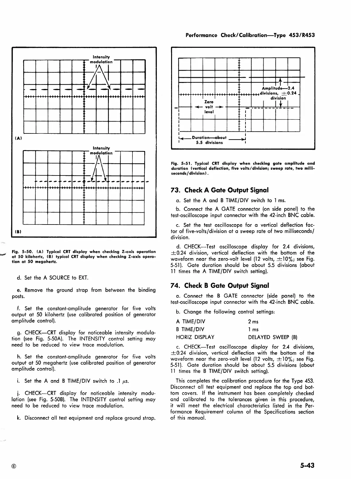
Fig.
5-51.
Typical
CRT
display
when
checking
gate
amplitude
and
duration
(vertical
deflection,
five
volts/division;
sweep
rate,
two
milli-
seconds/
division
l.
73. Check A Gate Output Signal
a. Set the A and B
TIME/DIV
switch to 1
ms.
b.
Connect the A
GATE
connector
(on
side panel) to the
test-oscilloscope input connector with the 42-inch
BNC
cable.
c.
Set the test oscilloscope for a vertical deflection fac-
tor of five-volts/division
at
a sweep rate of two milliseconds/
division.
d.
CHECK-Test oscilloscope display for
2.4
divisions,
-+-0.24
division, vertical deflection
with
the bottom of the
waveform near the zero-volt level
(12
volts,
-+-10%;
see
Fig.
5-51).
Gate
duration should be about 5.5 divisions (about
11
times the A
TIME/DIV
switch setting).
7 4. Check B Gate Output Signal
a. Connect the B
GATE
connector (side panel) to the
test-oscilloscope input connector with the 42-inch
BNC
cable.
b.
Change the following control settings:
A
TIME/DIV
B
TIME/DIV
HORIZ
DISPLAY
2
ms
1
ms
DELAYED
SWEEP
(B)
c.
CHECK-Test oscilloscope display for
2.4
divisions,
-+-0.24
division, vertical deflection with the bottom of the
waveform near the zero-volt
level
(12
volts, ± 10%; see
Fig.
5-51).
Gate
duration should be about 5.5 divisions (about
11
times the B
TIME/DIV
switch setting).
This
completes the calibration procedure for the Type
453.
Disconnect all test equipment and replace the top and bot-
tom
covers.
If
the instrument has been completely checked
and calibrated to the tolerances given
in
this
procedure,
it
will
meet the electrical characteristics listed
in
the
Per-
formance Requirement column of the Specifications section
of
this
manual.
5-43
 Loading...


