Type
453/R453
SECTION 2
OPERATING
INSTRUCTIONS
Change
information,
if
any,
affecting
this section
is
found
at
the
rear
of
the
manual.
General
To
effectively
use
the Type 453, the operation and capa-
bilities
of
the instrument must be known.
This
section de-
scribes the operation
of
the front-, side- and rear-panel
controls and connectors, gives first time and general operat-
ing information and lists
some
basic applications
for
this
instrument.
Front
Cover and Handle
The
front cover furnished with the Type
453
provides a
dust-tight seal around the front panel.
Use
the cover to
protect the front panel when storing
or
transporting the
instrument. The cover also provides storage space for probes
and other accessories
(see
Fig.
2-1
).
Fig.
2-1.
Accessory
storage
provided in front cover.
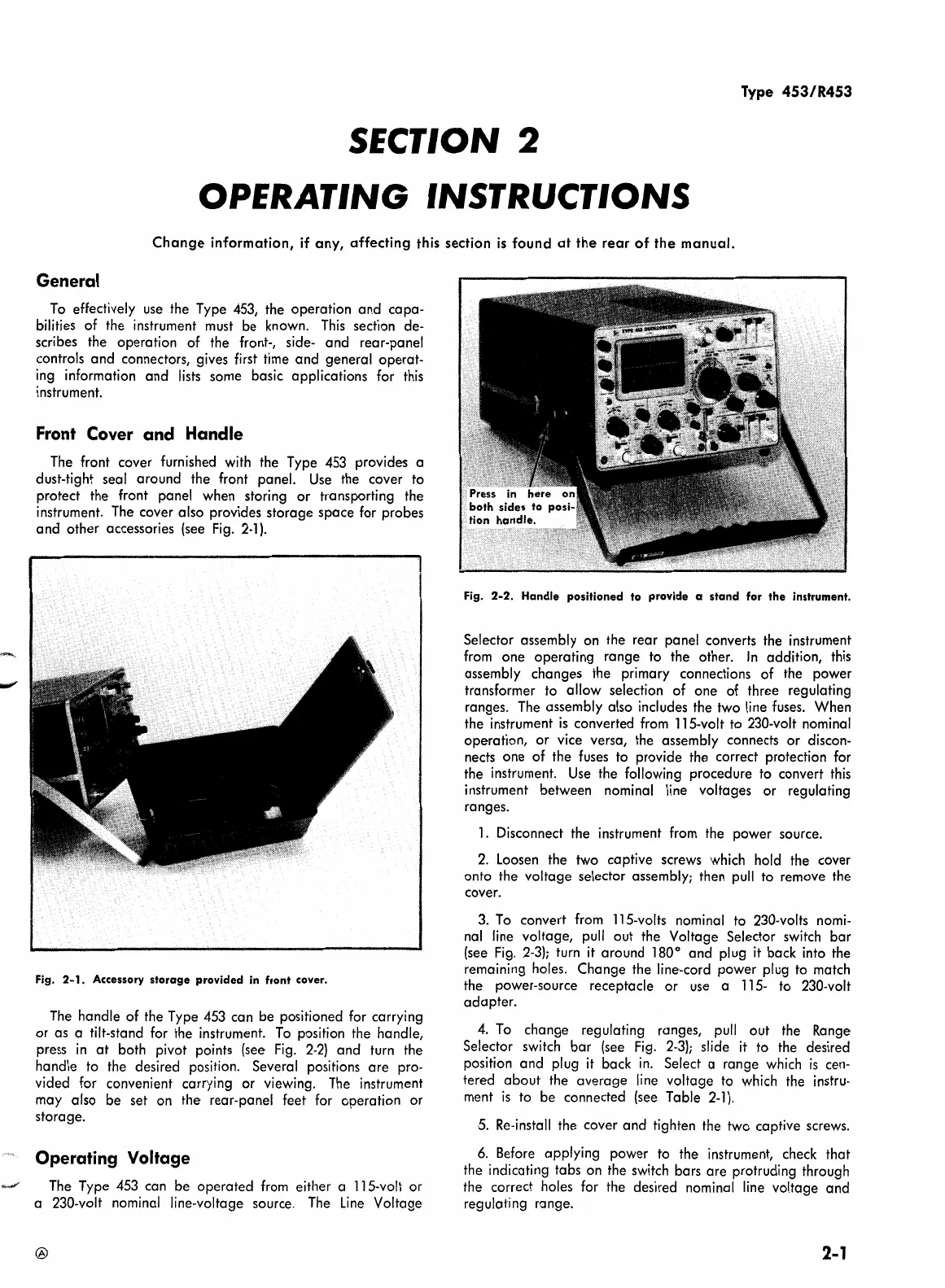
The
handle
of
the Type
453
can
be
positioned for carrying
or
as
a tilt-stand for the instrument.
To
position the handle,
press
in
at
both pivot points
(see
Fig.
2-2)
and turn the
handle to the desired position. Several positions are pro-
vided for convenient carrying
or
viewing.
The
instrument
may also be
set
on the rear-panel feet for operation or
storage.
Operating Voltage
The
Type 453
can
be operated from either a 115-volt
or
a 230-volt nominal line-voltage source.
The
Line
Voltage
®
Fig.
2-2.
Handle positioned to provide a
stand
for
the
instrument.
Selector assembly on the rear panel converts the instrument
from one operating range to the other.
In
addition, this
assembly changes the primary connections
of
the power
transformer to
allow
selection
of
one
of
three regulating
ranges.
The
assembly also includes the two line
fuses.
When
the instrument
is
converted from 115-volt to 230-volt nominal
operation,
or
vice versa, the assembly connects
or
discon-
nects
one
of
the
fuses
to provide the correct protection for
the instrument.
Use
the following procedure to convert this
instrument between nominal line voltages
or
regulating
ranges.
1.
Disconnect the instrument from the power source.
2.
Loosen
the two captive screws which hold the cover
onto the voltage selector assembly; then pull to remove the
cover.
3.
To
convert from 115-volts nominal to 230-volts nomi-
nal line voltage, pull out the Voltage Selector switch
bar
(see
Fig.
2-3);
turn
it
around 180° and plug
it
back into the
remaining holes. Change the line·-cord power plug to match
the power-source receptacle
or
use
a 115- to 230-volt
adapter.
4.
To
change regulating ranges, pull out the
Range·
Selector switch bar
(see
Fig.
2-3);
slide
it
to the desired
position and plug
it
back in. Select a range which
is
cen-
tered
about
the average line voltage to which the instru-
ment
is
to be connected
(see
Table
2-1
).
5.
Re-install the cover and tighten the two captive screws.
6.
Before applying power to the instrument, check that
the indicating tabs on the switch bars are protruding through
the correct holes for the desired nominal line voltage and
regulating range.
2-1