Performance
Check/Calibrati~n-Type
453/R453
.
...
-~
...
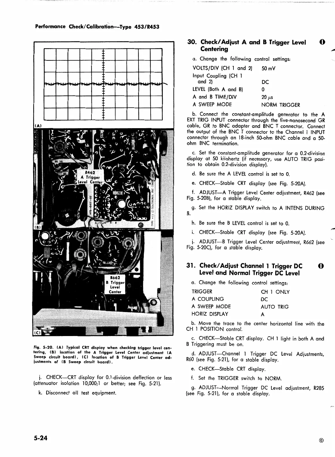
Fig.
5-20.
(Al
Typical
CRT
display when
checking
trigger
level
cen-
tering,
(8)
location
of
the
A Trigger Level Center
adjustment
(A
Sweep
circuit
board
l , (Cl location
of
B Trigger Level Center
ad-
justments
of
IB
Sweep
circuit
board).
j.
CHECK-CRT display for 0.1-division deflection or
less
(attenuator isolation
10,000;
1 or better; see
Fig.
5-21
).
k.
Disconnect all test equipment.
5-24
30.
Check/ Adiust A and B Trigger
Level
Centering
a. Change the following control settings:
VOLTS/DIV
(CH
1 and
2)
Input Coupling
(CH
1
and
2)
LEVEL
(Both
A and
B)
A and B
TIME/DIV
A
SWEEP
MODE
50mV
DC
0
20
µ.s
NORM
TRIGGER
0
b.
Connect the constant-amplitude generator to the A
EXT
TRIG
INPUT
connector through the five-nanosecond
GR
cable,
GR
to
BNC
adapter and
BNC
T connector. Connect
the output
of
the
BNC
T connector to the Channel 1
INPUT
connector through an
18-inch
50-ohm
BNC
cable and a
50-
ohm
BNC
termination.
c.
Set the constant-amplitude generator for a 0.2-division
display
at
50
kilohertz
(if
necessary,
use
AUTO
TRIG
posi-
tion
to
obtain 0.2-division display).
d.
Be
sure the A
LEVEL
control
is
set
to
0.
e. CHECK-Stable
CRT
display
(see
Fig.
5-20A).
f.
ADJUST-A Trigger
Level
Center adjustment,
R462
(see
Fig.
5-20B),
for a stable display.
g. Set the
HORIZ
DISPLAY
switch
to
A
INTENS
DURING
B.
h.
Be
sure the B
LEVEL
control
is
set
to
0.
1.
CHECK-Stable
CRT
display
(see
Fig.
5-20A).
j.
ADJUST-B Trigger
Level
Center adjustment,
R662
(see
Fig.
5-20C),
for a stable display.
31.
Check/ Adiust Channel 1 Trigger DC 0
Level
and Normal Trigger
DC
Level
a. Change the following control settings:
TRIGGER
A
COUPLING
A
SWEEP
MODE
HORIZ
DISPLAY
CH
1
ONLY
DC
AUTO
TRIG
A
b.
Move the trace
to
the center horizontal
line
with
the
CH
1
POSITION
control.
c.
CHECK-Stable
CRT
display.
CH
1 light
in
both A and
B Triggering
must
be
on.
d.
ADJUST-Channel 1 Trigger
DC
Level
Adjustments,
R60
(see
Fig.
5-21
),
for
a stable display.
e.
CHECK-Stable
CRT
display.
f.
Set the
TRIGGER
switch
to
NORM.
g.
ADJUST-Normal Trigger
DC
Level
adjustment,
R285
(see
Fig.
5-21
),
for a stable display.
©
 Loading...


