Removal and Installation Procedures
AFG3000 Series Arbitrary/Function Generators Service Manual 6-21
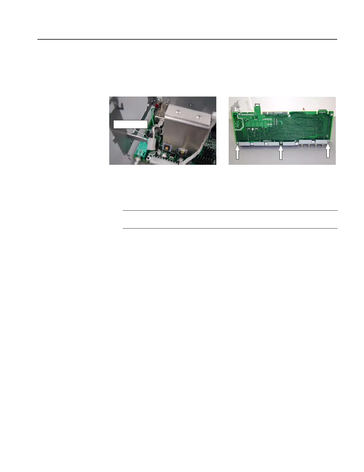
7. Remove the three screws from the bottom side that attach the CPU board to the
rear sub-panel.
8. Remove the CPU board from the rear sub-panel.
Figure 6-17: CPU board removal
Installation. To install, reverse this procedure. Remember to attach the wave
washers and the insulator bushings.
A82 BNC Insulator Board
You will need a torque-limiting Torx T-15 screwdriver, a torque wrench, and a 16 mm
(5/8 inch) deep socket.
Removal. To remove the A82 BNC Insulator board, follow these steps:
1. Remove the CH1 Add Input BNC connector and the EXT Modulation CH2
Input BNC connector using the procedures on page 6-20.
2. Remove the nuts and wave washers of the EXT Modulation CH1 Input, the
Ext Ref Input, and the Ext Ref Output connectors using the procedures on
page 6-20.
3. Remove the three screws that attach the A82 BNC Insulator board to the rear
sub-panel.
4. Remove the A82 BNC Insulator board from the rear sub-panel.
Installation. To install, reverse this procedure.
AC input cable
NOTE. After you replace the CPU board, you must set the serial number. Refer to
Setting the Serial Number on page 5-12.
 Loading...


