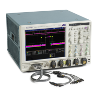
Brief Procedures (MSO70000/C Series, DSA/DPO70000B/C Series, and DPO7000 Series)
6. Verify that the
delayed trigger system operates:
a. Set up the delayed trigger:
Pull down the Trig menu and select A – B Trigger Sequence. . . .This
displays the A →B Sequence tab of the trigger setup control window.
Click the Trig After Time button under A Then B.
Click the B Trig Level control in the control window.
Set the front-panel trigger mode to Norm.
b. Confirm that the following statements are true:
The trigg
er-level readout for the B trigger system changes as you turn
the lower multipurpose knob.
As you ro
tate the lower multipurpose knob, the square-wave signal
can become triggered and untriggered. (Leave the signal triggered.)
c. Verify
the delayed trigger counter:
Double click the Trig Delay control to pop up a numeric keypad for
that c
ontrol.
Click the keypad to enter a trigger delay time of 1 second (click 1
and No
ne) and then click Enter.
Verify that the trigger Ready indicator on the front panel flashes about
once
every second as the waveform is updated on-screen.
7. Remove the test hookup: Disconnect the test hookup from the instrument.
Ve
rifytheFileSystem
Equipment required Prerequisites
< 4 GHz models: One precision 50 Ω coaxial
cable (Item 4)
<4
GHz models: One BNC to Minigrabber
adapter (item 18)
≥ 4 GHz models: One SMA cable (item 21)
≥
4 GHz models: One adapter (item 19)
Non
e
1. Initialize the instrument: Push the front-panel Default Setup button.
2. Hook up the s ignal source: Connect the probe compensation or fast edge
output to the Ch 1 input as shown in the following.
MSO70000/C, DSA70000B/C, DPO7000B/C, DPO7000, MSO5000, DPO5000 Series 3–13

 Loading...


