Performance Tests (MSO/DPO5000 Series)
11. Repeat the proc
edure for all remaining channels as follows:
a. Push the front-panel button to deselect the channel that you have already
tested.
b. Push the front-panel channel button for the next channel to be tested.
c. Connect the signal source to the input for that channel.
d. Repeat the procedure from step 5 until all channels have b een tested.
12. Press the Menu Off button.
Check Digital Threshold Accuracy (MSO5000 only)
For the MSO5000 se ries only, this test checks the threshold accuracy of the d igital
channels. This procedure applies to digital channels D0 through D15, and to
channel threshold values of 0 V and +4 V.
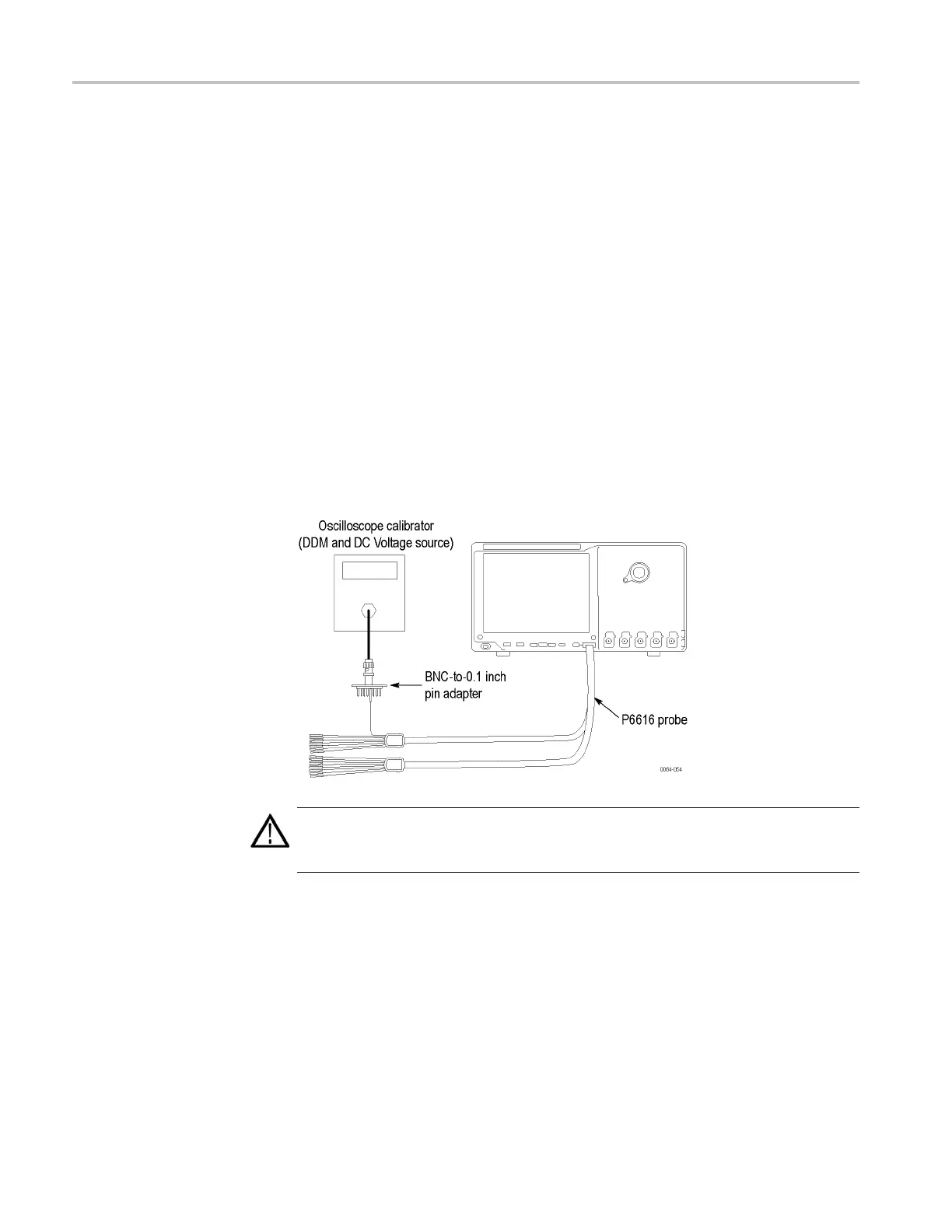
1. Connect the P6616 digital probe to the MSO5000 series instrument.
WARNING. The generator is capable of pro viding dangerous voltages. Be sure to
set the generator to off or 0 volts before connecting, disconnecting, and/or moving
the test hookup during the performance of this procedure.
2. Connect the DC voltage source to the digital channel D0.
If you are using the Fluke 9500 calibrator a s the DC voltage source, connect
the calibrator head to the digital channel D0, using the BNC-to-0.1 inch
pin adapter listed in the Required Equipment table. (See Table 4-1 on
page 4-1.) Be sure to connect channel D0 from the probe connector to both
the c orresponding signal pin and to a ground pin on the adapte
r.
3. Push the front-panel Default S etup button.
4–44 MSO70000/C, DSA70000B/C, DPO7000B/C, DPO7000, MSO5000, DPO5000 Series
 Loading...


