Home
Tektronix
Test Equipment
DPO70000 Series
Tektronix DPO70000 Series Technical Reference
4
of 1
of 1 rating
262 pages
Give review
Manual
Specs
To Next Page
To Next Page
To Previous Page
To Previous Page
Loading...
Performance
T
ests
(MSO70000/C
Series,
DSA/
DPO700
00B/C
Series,
and
DPO7000
Series)
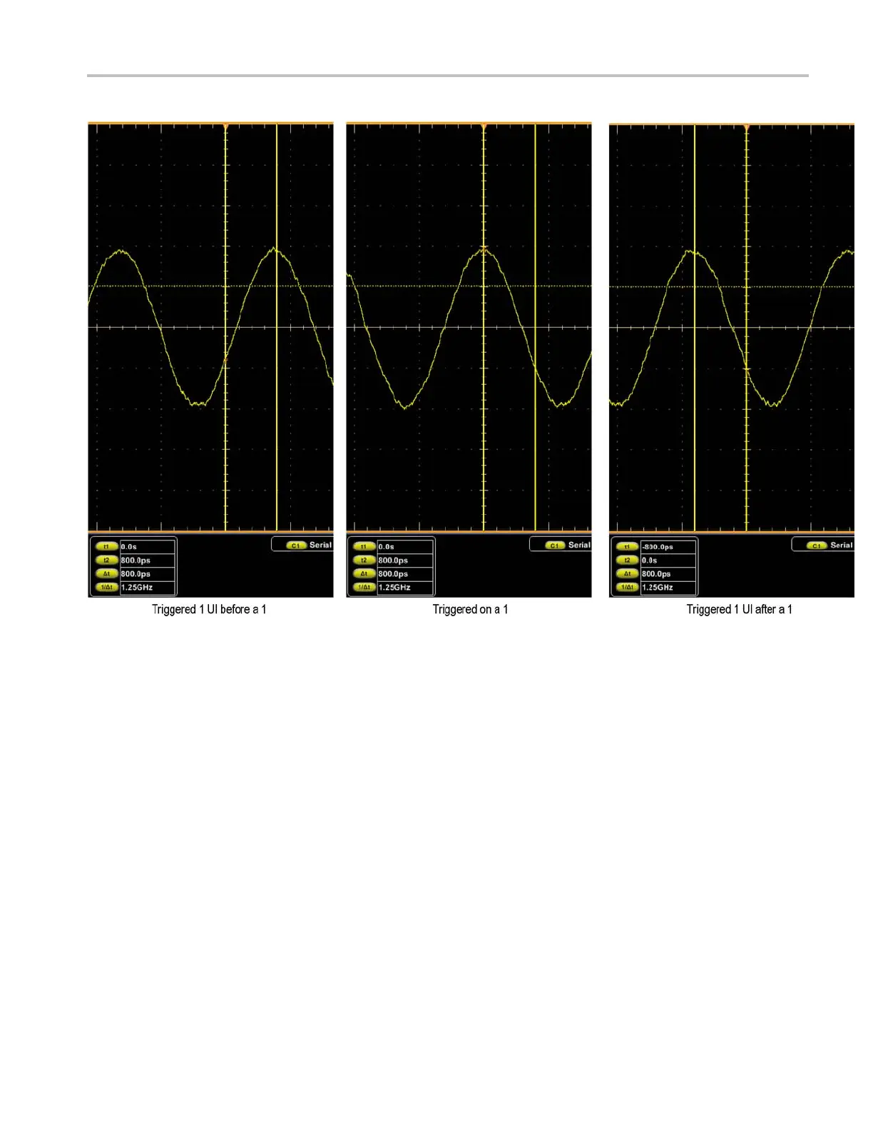
Figure
3-35:
Isolated
1
triggering
MSO70000/C,
DSA70000B/C,
DPO7000B/C,
DPO7000,
MSO5000,
DPO5000
Series
3–109
204
206
Table of Contents
Default Chapter
7
Table of Contents
7
General Safety Summary
12
Specifications (MSO70000/C Series, DSA/DPO70000B/C Series, and DPO7000 Series)
15
Series,Anddpo7000Series)
17
Performanceverification(Mso70000/Cseries,Dsa/Dpo70000B/C
17
Specifications (MSO70000/C Series, DSA/DPO70000B/C Series, and DPO7000 Series)
17
Table 1-1: Channel Input and Vertical Specifications, All MSO70000/C, DSA/DPO70000B/C, and
17
DPO7000 Series Models
48
Table 1-2: Horizontal and Acquisition System Specifications, All MSO70000/C, DSA/DPO70000B/C, and
50
Table 1-3: Trigger Specifications, All MSO70000/C, DSA/DPO70000B/C, and DPO7000 Series
57
Table 1-4: Serial Trigger Specifications, All MSO70000/C and DSA/DPO70000B/C Series Models
64
Table 1-5: Digital Acquisition Specifications (MSO70000/C Series)
67
Table 1-6: Input/Output Port Specifications, All MSO70000/C, DSA/DPO70000B/C, and DPO7000 Series
68
Models
71
Table 1-7: Data Storage Specifications, All MSO70000/C, DSA/DPO70000B/C, and DPO7000 Series
72
Table 1-8: Power Source Specification, All MSO70000/C, DSA/DPO70000B/C, and DPO7000 Series
72
Table 1-9: Mechanical Specifications, All MSO70000/C, DSA/DPO70000B/C, and DPO7000 Series
73
Table 1-10: Environmental Specifications, All MSO70000/C, DSA/DPO70000B/C, and DPO7000 Series
74
Specifications (MSO/DPO5000 Series)
75
Specifications (MSO/DPO5000 Series)
77
Table 2-1: Analog Channel Input and Vertical Specification
77
Table 2-2: Horizontal and Acquisition System Specifications
85
Table 2-3: Trigger Specifications
87
Table 2-4: Digital Acquisition Specifications, MSO5000 Series
91
Table 2-5: P6616 Digital Probe Specifications
91
Table 2-6: Display Specifications
92
Table 2-7: Input/Output Port Specifications
92
Table 2-8: Data Storage Specifications
93
Table 2-9: Power Source Specifications
93
Table 2-10: Environmental Specifications
93
Table 2-11: Mechanical Specifications
94
Dpo7000Series)
95
Performance Verification (MSO70000/C Series, DSA/DPO70000B/C Series, and DPO7000 Series)
95
Performance Verification (MSO70000/C Series, DSA/DPO70000B/C Series, and DPO7000 Series)
97
Conventions
98
Figure 3-1: Toolbar and Menu Bar (< 4 Ghz Models Shown)
99
Brief Procedures (MSO70000/C Series, DSA/DPO70000B/C Series, and DPO7000 Series)
100
Self Tests
100
Functional Tests
101
Figure 3-2: Universal Test Hookup for Functional Tests - Ch 1 Shown
102
Verify All Analog Input Channels
102
Figure 3-3: Channel Button Location
103
Table 3-1: Vertical Settings
104
Verify the Time Base
105
Figure 3-4: Setup for Time Base Test
106
Figure 3-5: Setup for Trigger Test
108
Verify the a (Main) and B (Delayed) Trigger Systems
108
Verify the File System
109
Figure 3-6: Setup for the File System Test
110
Figure 3-7: Setup for the Digital Channels Test
111
Verify the Digital Channels (MSO70000 Series Only)
111
Performance Tests (MSO70000/C Series, DSA/DPO70000B/C Series, and DPO7000 Series)
114
Prerequisites
114
Equipment Required
115
Table 3-2: Test Equipment
115
Test Record
118
Table 3-3: Test Record
119
Signal Acquisition System Checks
138
Figure 3-8: Initial Test Hookup
139
Table 3-4: DC Voltage Measurement Accuracy
140
Figure 3-9: Measurement of DC Accuracy at Maximum Offset and Position
142
Check DC Gain Accuracy, ≥ 4 Ghz Models
144
Table 3-5: Gain Accuracy
145
Figure 3-10: Measurement of DC Gain Accuracy
151
Figure 3-11: Initial Test Hookup
152
Check Offset Accuracy ≥ 4 Ghz Models
152
Table 3-6: Offset Accuracy
153
Figure 3-12: Measurement of Offset Accuracy
154
Check Analog Bandwidth, < 3.5 Ghz Models
156
Figure 3-13: Initial Test Hookup
157
Table 3-7: Analog Bandwidth, < 3.5 Ghz Models
158
Figure 3-14: Measurement of Analog Bandwidth
159
Check Channel Bandwidth, ≥ 3.5 Ghz Models
161
Figure 3-15: Initial Test Hookup
162
Table 3-8: Channel Bandwidth ≥4 Ghz Models
163
Table 3-9: Channel Bandwidth 3.5 Ghz Model
163
Figure 3-16: Measurement of Analog Bandwidth
165
Check Input Resistance, ≥ 4 Ghz Models
167
Figure 3-17: Initial Test Hookup
167
Figure 3-18: Initial Test Hookup
169
Time Base System Checks
169
Figure 3-19: Initial Test Hookup
170
Figure 3-20: Final Test Hookup
171
Check Delta Time Measurement Accuracy, < 4 Ghz Models
172
Figure 3-21: Delta Time Accuracy Test Hookup
172
Table 3-10: Delta Time Measurement Settings
174
Check Delta Time Measurement Accuracy, ≥ 4 Ghz Models
176
Figure 3-22: Delta Time Accuracy Test Hookup
176
Table 3-11: Delta Time Measurement Settings
177
Figure 3-23: Initial Test Hookup
181
Trigger System Checks
181
Figure 3-24: Measurement of Time Accuracy for Pulse and Glitch Triggering
182
Check Sensitivity, Edge Trigger, DC Coupled
185
Figure 3-25: Initial Test Hookup
186
Figure 3-26: Measurement of Trigger Sensitivity - 50 Mhz Results Shown
188
Table 3-12: Trigger Settings for ≥ 4 Ghz Models
191
Figure 3-27: Initial Test Hookup
194
Output Signal Checks
194
Figure 3-28: Measurement of Trigger out Limits
195
Check Probe Compensation or Fast Edge Output
196
Figure 3-29: Initial Test Hookup
196
Figure 3-30: Measurement of Probe Compensator Frequency
197
Figure 3-31: Subsequent Test Hookup
198
Figure 3-32: Measurement of Probe Compensator Amplitude
198
Figure 3-33: Initial Test Hookup
200
Serial Trigger Checks (Optional on some Models)
200
Table 3-13: Serial Pattern Data
201
Figure 3-34: Isolated 0 Triggering
203
Table 3-14: Word Recognizer Data
204
Figure 3-35: Isolated 1 Triggering
205
Check Serial Trigger Clock Recovery Range
206
Figure 3-36: Initial Test Hookup
206
Table 3-15: Clock Recovery Input Frequencies and Baud Rates
208
Figure 3-37: Clock Recovery
209
Figure 3-38: Sine Wave Generator Leveling Equipment Setup
210
Figure 3-39: Equipment Setup for Maximum Amplitude
212
Performance Verification (MSO/DPO5000 Series)
215
Test Record
216
Performance Tests (MSO/DPO5000 Series)
239
Self Test
240
Check Input Impedance (Resistance)
241
Check DC Balance
242
Check DC Gain Accuracy
244
Table 4-2: Gain Expected Worksheet
246
Check Offset Accuracy
247
Check Analog Bandwidth
249
Table 4-3: Maximum Bandwidth Frequency Worksheet
251
Check Random Noise, Sample Acquisition Mode
252
Check Sample Rate and Delay Time Accuracy
254
Check Delta Time Measurement Accuracy
256
Check Digital Threshold Accuracy (MSO5000 Only)
258
Check Trigger out
261
Other manuals for Tektronix DPO70000 Series
User Manual
213 pages
Quick Start User Manual
164 pages
Service Manual
167 pages
Programmer's Manual
733 pages
4
Based on 1 rating
Ask a question
Give review
Questions and Answers:
Need help?
Do you have a question about the Tektronix DPO70000 Series and is the answer not in the manual?
Ask a question
Tektronix DPO70000 Series Specifications
General
Brand
Tektronix
Model
DPO70000 Series
Category
Test Equipment
Language
English
Related product manuals
Tektronix DPO7000 Series
213 pages
Tektronix DPO70000C Series
222 pages
Tektronix DPO70000SX Series
230 pages
Tektronix DPO70000C/DX Series
1002 pages
Tektronix DPO7054
213 pages
Tektronix DPO7054C
222 pages
Tektronix DPO70804C
222 pages
Tektronix DPO7354
213 pages
Tektronix DPO7254
213 pages
Tektronix DPO7354C
222 pages
Tektronix DPO75902S
920 pages
Tektronix DPO71254C
222 pages