Calibration
www.ti.com
80
SLUUBD3D–September 2015–Revised September 2018
Submit Documentation Feedback
Copyright © 2015–2018, Texas Instruments Incorporated
Manufacture Production
1. Apply a known voltage in mV to the battery terminals on which the resistor divider is connected.
2. Divide the known battery voltage by the number of cells configured in AFE Cell Map. This would be
Actual Avg Cell Voltage.
3. Read ExtAveCellVoltage().
4. Calculate the Ext Cell Divider Gain.
• New Ext Cell Divider Gain = (Old Ext Cell Divider Gain × Actual Avg Cell Voltage)/Measured
Avg Cell Voltage
5. Update Ext Cell Divider Gain in data flash.
12.2.3 VAUX Voltage Calibration
The bq78350-R1 can be configured with an auxiliary voltage measurement input. This measurement has
its own calibration procedure, as follows:
1. Apply a known voltage in mV to the VAUX input.
2. Read VAUXVoltage().
3. Calculate the VAUX Gain.
• New VAUX Gain = (Old VAUX Gain/VAUX Voltage)
4. Update VAUX Gain in data flash.
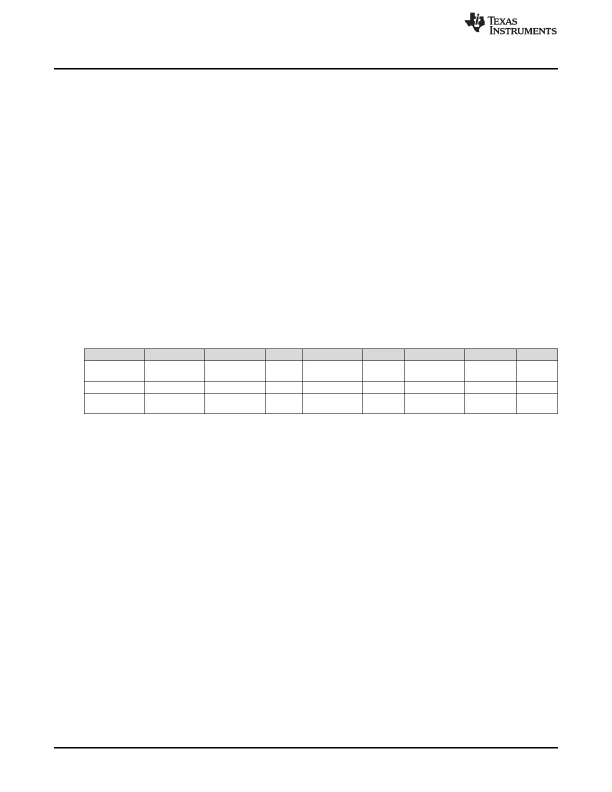
12.2.4 Voltage Calibration Data Flash
(1)
Setting this value to 0 causes the gauge to use the internal factory calibration default.
Class Subclass Name Type Length in Bytes Min Max Default Unit
Calibration Voltage
Cell1 Offset to
Cell15 Offset
Integer 1 –128 127 0
(1)
—
Calibration VAUX Voltage VAUX Gain Integer 4 0 10000 5000 —
Calibration Ext Cell Voltage
Ext Ave Divider
Gain
Integer 2 0 32767 5000 —
12.2.5 Current Calibration
12.2.5.1 CC Offset Calibration
1. Apply a known current of 0 mA, and ensure no current is flowing through the sense resistor connected
between the SRP and SRN pins.
2. If ManufacturerStatus()[CAL] = 0, send 0x002D to ManufacturerAccess() to enable the [CAL] flag.
3. Send 0xF082 to ManufacturerAccess() to enable factory calibrated CC output on ManufacturerData().
4. Poll ManufacturerData() until ZZ increments by 2 before reading data.
5. Obtain the factory calibrated conversion readings of current from ManufacturerData():
• FCAL
CC
= GGgg of ManufacturerData()
Is FCAL
CC
< 0x8000? If yes, use FCAL
CC
; otherwise, FCAL
CC
= –(0xFFFF – AAaa + 0x0001).
6. Average several readings for higher accuracy. Poll ManufacturerData() until ZZ increments to indicate
that updated values are available:
• FCAL
CC
= [FCAL
CC
(reading n) + … + FCAL
CC
(reading 1)]/n
7. Read Coulomb Counter Offset Samples from data flash.
8. Calculate offset value:
• CC offset = FCAL
CC
× (Coulomb Counter Offset Samples)
9. Write the new CC Offset value to data flash.
10. Re-check the current reading and if it is not accurate, repeat the steps.
11. Send 0x002D to ManufacturerAccess() to clear the [CAL] flag if all calibration is complete.
 Loading...