www.ti.com
Display Activation
85
SLUUBD3D–September 2015–Revised September 2018
Submit Documentation Feedback
Copyright © 2015–2018, Texas Instruments Incorporated
Display Port
If [LEDRCA] = 1 and the BatteryStatus() [RCA] change from 0 to 1, the LED display will also flash at the
LED Flash Rate according to the LED Flash Alarm.
13.2.2 LCD Display Activation
The LCD is activated all the time during operation except:
• If SafetyStatus() [CUV] flag is set.
• If the device is in the SHUTDOWN power mode.
• If LCD_SLEEP_DIS is set AND the device is in the SLEEP power mode.
13.3 State-Of-Charge Display
The state-of-charge can display RelativeStateOfCharge() or (AbsoluteStateOfCharge()/DesignCapacity()),
selectable with LED Configuration [LEDMODE].
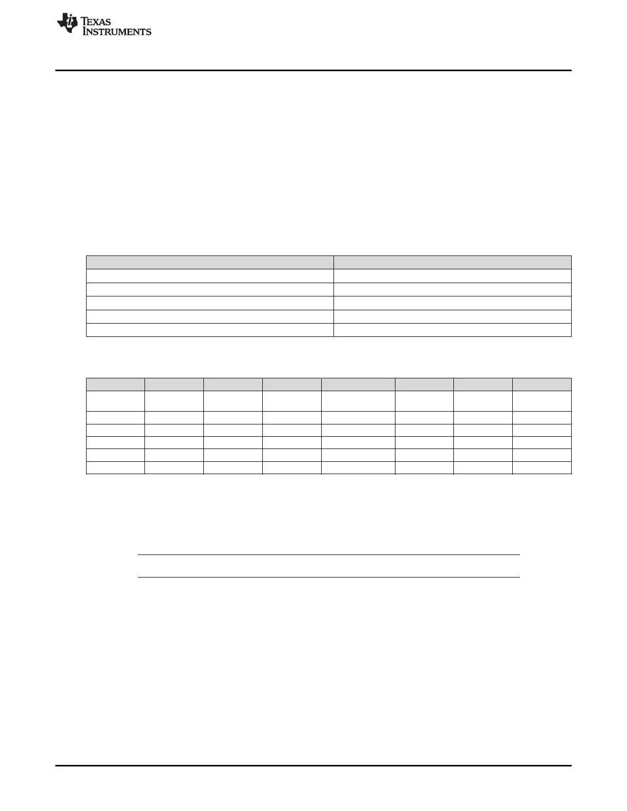
LED/LCD Segment Output ON State-Of-Charge
LED1/LCD1 LED Thresh 1
LED2/LCD2 LED Thresh 2
LED3/LCD3 LED Thresh 3
LED4/LCD4 LED Thresh 4
LED5/LCD5 LED Thresh 5
Table 13-1. Display Thresholds
Class Subclass Name Format Length in Bytes Min Max Default
LED Support LED Config
LED Flash
Alarm
Integer 1 0% 100% 10%
LED Support LED Config LED Thresh 1 Integer 1 0% 100% 0%
LED Support LED Config LED Thresh 2 Integer 1 0% 100% 20%
LED Support LED Config LED Thresh 3 Integer 1 0% 100% 40%
LED Support LED Config LED Thresh 4 Integer 1 0% 100% 60%
LED Support LED Config LED Thresh 5 Integer 1 0% 100% 80%
The default settings are for a 5-LED/LCD segment display; however, if fewer LEDs/LCD segments are
required, that is, when extra Host Controlled GPIOs are required, then less LEDs/LCD segments can be
used. In this case, the lower LEDs/LCD segments should be used with the unused LEDs/LCD segments
being set to 100%. For example, in a 3-LED case, LED1, LED2, and LED3 should be used and can be
configured for 0, 33%, and 66%, respectively, with LED4 and LED5 set to 100%.
NOTE: Unused LED settings must be set to 100% even if the pin is not used.
13.4 LED and LCD Display Configuration
All data flash settings are available through the LED Support:LED Config subclass. When the display is
enabled for LEDs, the following configuration options are available:
• LED Blink Period—During charging, the top LED segment flashes with the LED Blink Period time
period, and lower LEDs will be fully ON. For example, if battery charge is 36% and the display uses
five LEDs, LED 1 will be ON and LED 2 will blink. [LEDRCA] will override this setting if active.
• LED Flash Period—During discharge alarm, the remaining LED segments flash with the LED Flash
Period time period: for example, if battery charge is 36% and the display uses five LEDs, LED 1 and
LED 2 will blink.
• LED Delay—An activation delay from one LED to another LED can be set with this value. For LCD,
this configuration is not used because the display is always active.
• LED Hold Time—After display activation, the display will stay on for the LED Hold Time period. For
 Loading...