2GM
2-3-19
Developing
roller
Bias PWB
Engine PWB
Regist-
ration
sensor
Developing bias
output circuit
FAN1
FAN
FAN2
P
A
P
E
R
N
SWIN
RESIT
TONEREPY
HVCLK
RTHVDR,
HVISEL, PSEL1
EXTIN, THERM
Casette
switch
Paper
sensor
+5V
TONER
Toner
sensor
275 V DC + AC
+5V
+5V
+5V
+24V3
+24V2+24V2+24V2
+24V1
SLEEP
+24V3
HEATN, ZCROSS, SLEEPN
High
voltage
PWB
Power
supply
PWB
+5V
+24V2
+24V3
FET
YC301
YC305
YC302
YC303
YC304
SW301
T301
VR301
U301
13
A1
B1
A12
B12
1
12
16
115
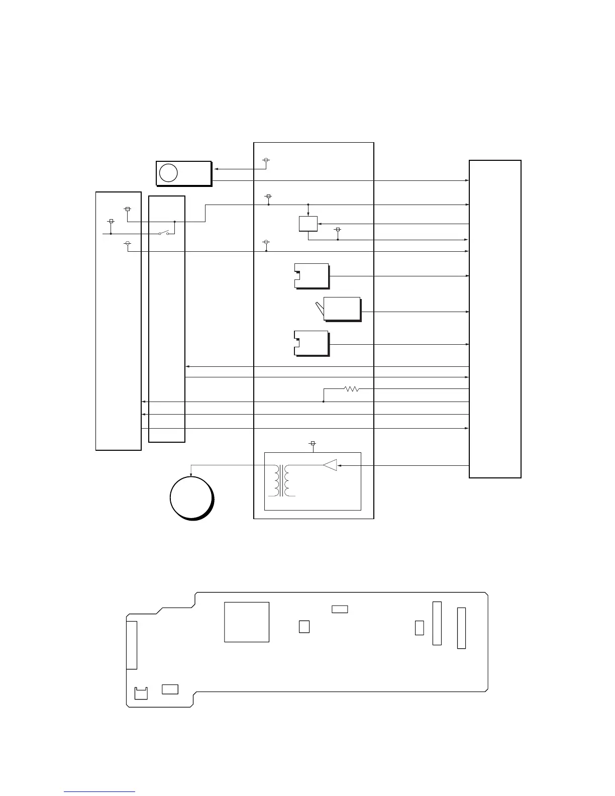
Figure 2-3-11 Bias PWB circuit block diagram
2-3-4 Bias PWB
The bias PWB contains the developing bias output circuit, registration sensor, paper empty sensor, and the cassette switch.
It also provides a liaison connection to the high voltage PWB, power supply, and the toner sensor.
Figure 2-3-12 Bias PWB silk-screen diagram
 Loading...