2GM
2-3-24
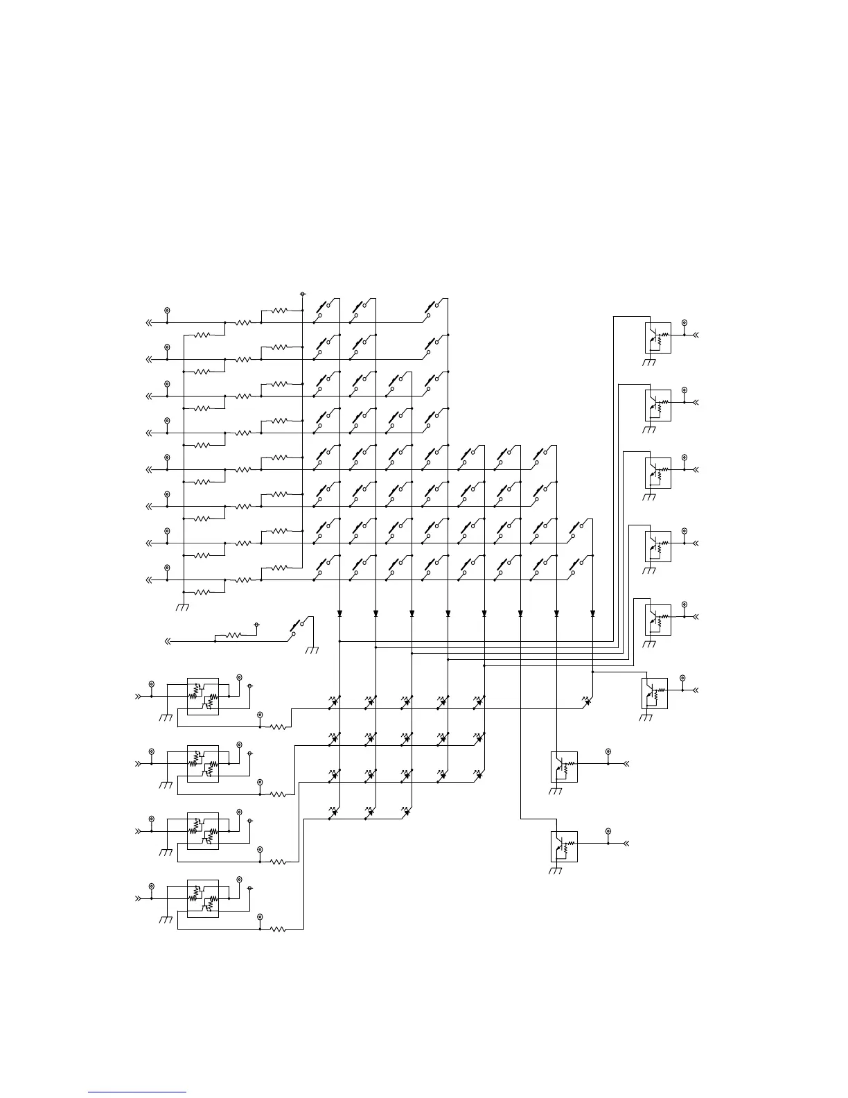
Figure 2-3-18 Operator PWB circuit block diagram
SGND
SGND
+5V
SGND
+5V
SGND
+5V
SGND
+5V
SGND
SGND
SGND
SGND
SGND
SGND
SGND
SGND
SGND
+3.3V
+5V
ENGY_KEY
LED3
LED2
LED1
LED0
SCAN6
SCAN7
SCAN5
SCAN0
SCAN4
SCAN2
SCAN1
SCAN3
KEYIN6
KEYIN5
KEYIN4
KEYIN3
KEYIN2
KEYIN1
KEYIN0
KEYIN7
SW
LED
R77
D5
21
TP194
K40
D27
LEDG
D4
21
R78
R72
D22
LEDG
TP159
K19
K28
K1
K15
K29
K35
Q6
1
2
3
Q13
4
1
3
2 5
6
R74
R98
R89
K31
Q11
4
1
3
2 5
6
TP193
K24
Q5
1
2
3
K14
K3
D3
21
R94
D11
LEDG
TP172
K10
D19
LEDG
R71
TP208
R86
K39
K5
K45
D26
LEDR
TP163
R79
R68
R81
TP178
R66
D13
LEDG
D14
LEDG
K43
K12
K9
TP177
K25
Q8
4
1
3
2 5
6
K34
R90
TP202
D20
LEDG
D12
LEDG
R83
K22
D6
21
K26
Q12
1
2
3
1
2
3
R87
D29
LEDG
TP211
K38
Q7
K13
R75
TP165
K8
K2
Q4
1
2
3
D2
21
K33
TP207
R76
TP169
K42
TP199
K11
K27
R96
TP201
TP160
TP196
K20
K6
D7
21
R73
D21
LEDG
R88
R69
K32
D18
LEDG
K37
TP210
D15
LEDG
Q10
1
2
3
K7
R84
D23
LEDG
TP191
D9
LEDG
R85
K18
D1
21
R70
Q3
1
2
3
R67
K17
R80
K23
K41
TP206
D28
LEDG
TP175
K21
TP200
TP195
D16
LEDG
D8
21
R82
K16
K30
K36
TP171
TP157
TP166
K4
D10
LEDG
TP212
R97
K44
D17
LEDG
Q9
1
2
3
TP205
Q15
4
1
3
2 5
6
2-3-7 Operation PWB
The operation PWB consists of key switches and LEDs. The lighting of LEDs is determined by scan signals (SCAN0 to
SCAN7) and LED lighting selection signals (LED0 to LED3) from the main PWB. The key switches operated are identified by
the scan signals (SCAN0 to SCAN7) and the return signals (KEYIN0 to KEYIN7).
As an example, to light LEDG9, the LED lighting selection signal (LED3) should be driven low in synchronization with a low
level on the scan signal (SCAN0). LEDs can be lit dynamically by repeating such operations.
As another example, if K9 is pressed, the corresponding key switch is turned on feeding the low level of the scan signal
(SCAN6) back to the main PWB via the return signal (KEYIN7). The main PWB locates the position where the line outputting
the scan signal and the line inputting the return signal cross, and thereby determines which key switch was operated.

 Loading...