2GM
2-3-20
Control
and
driver
circuit
Transfer bias
output
positive voltage
circuit
MHVDR1,2
THVDR,
RTHVDR
PSEL1
HVISEL
+24V2
+24V2
+24V2
+24V3
+24V1
+5V
+5V
ZCROSS,
THERM, EXITN
Interlock switch
High voltage PWB
Bias PWB
Power supply PWB
Engine PWB
Main
charger
Transfer
roller
High voltage output circuit
FAN,
HEATN, SLEEPN
Control
and
driver
circuit
FET
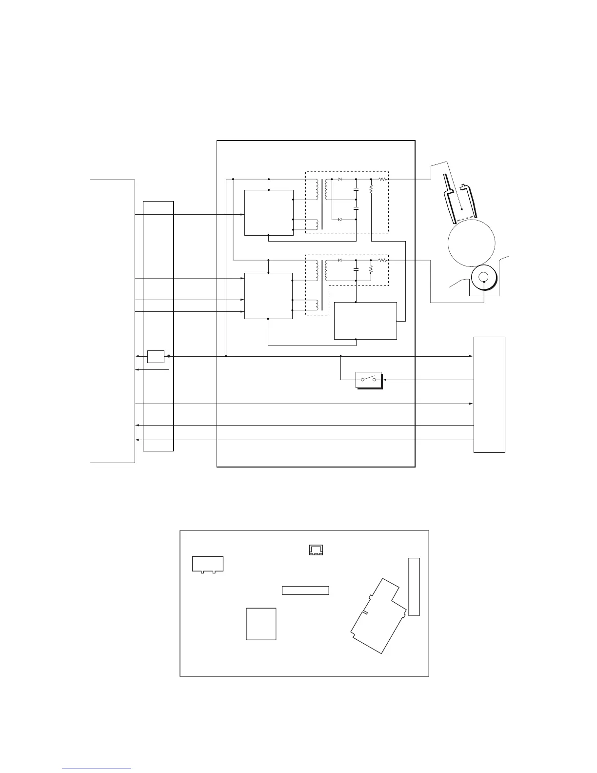
2-3-5 High voltage PWB
The high voltage PWB contains the high voltage output circuit, interlock switch circuit as well as providing a liaison
connection with the power supply PWB, bias PWB, and the engine PWB.
Figure 2-3-13 High voltage PWB circuit block diagram
Figure 2-3-14 High voltage PWB silk-screen diagram
SW1
YC1
T201
T101
YC2
YC3
 Loading...