EasyManua.ls Logo

Vertiv Liebert iCOM DP400/500 User Manual

Vertiv Liebert iCOM DP400/500
180 pages
To Next Page IconTo Next Page
To Previous Page IconTo Previous Page
Page #131 background imageLoading...
Page #131 background image
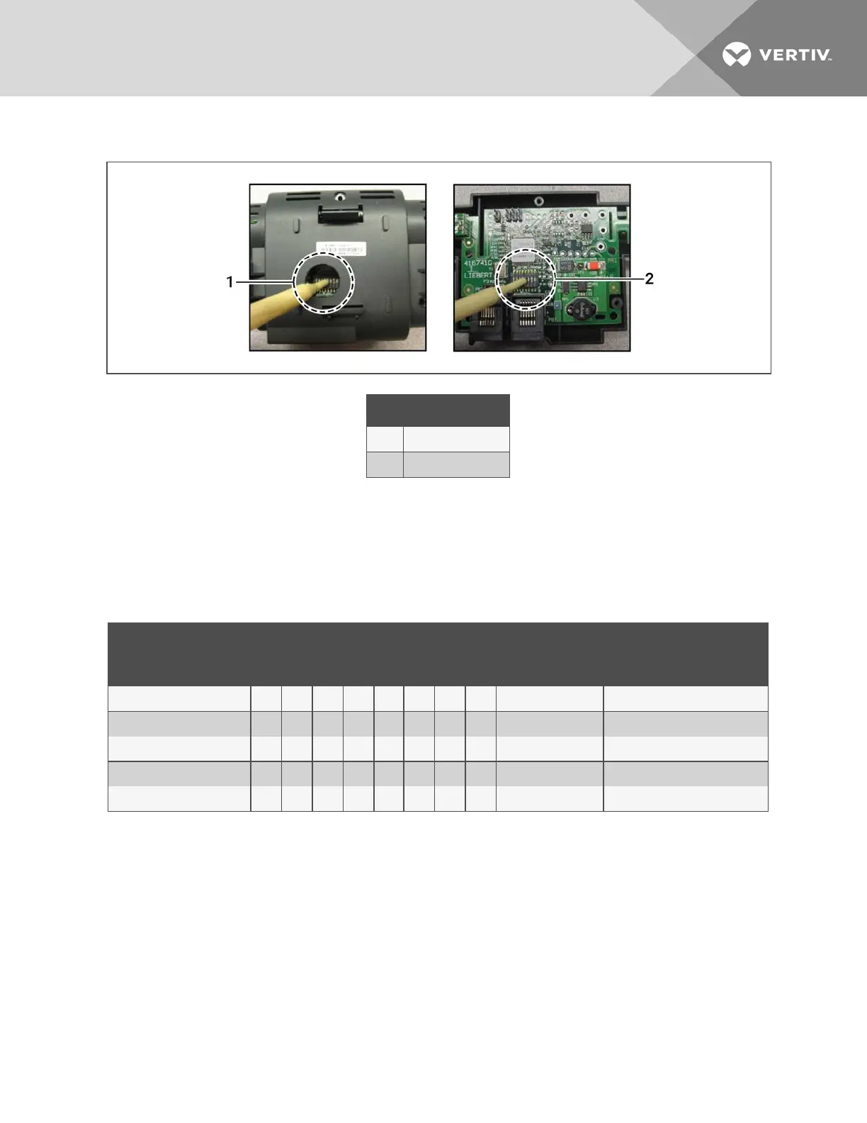
Figure 12.16 DIP Switch Opening/DIP Switches Inside of 2T Sensor
Item Description
1 Hole in sensor housing
2 Cover removed
3. Referring to Table 12.4 below, and using the non-conductive tool, set the DIP switches for each sensor to its
number in the chain (from sticker applied in step 1).
Figure 12.17 on the next page, shows a representation of the DIP switches.
4. Confirm that the DIP switches are set correctly for each sensor, and replace the housing cover if necessary.
Sensor Number/Address
DIP Switch Position
CANbus Node ID Alternate Use
1 2 3 4 5 6 7 8
A On Off Off Off On Off Off Off 17 Temperature/Humidity
B Off On Off Off On Off Off Off 18 Temperature/Humidity
C On On Off Off On Off Off Off 19 Temperature/Humidity
D Off On On On On Off Off Off 30 Fluid inlet/outlet temperature
E On On On On On Off Off Off 31 Fluid inlet/outlet temperature
Table 12.4 DIP Switch Settings for Supply Air Aggregation Sensors
13 Hardware Installation
123

Table of Contents

Questions and Answers:

Vertiv Liebert iCOM DP400/500 Specifications

General IconGeneral
BrandVertiv
ModelLiebert iCOM DP400/500
CategoryThermostat
LanguageEnglish

Summary

Getting Started with iCOM

User Operation

Viewing and Editing Setpoints

Guides on how to view and modify cooling unit setpoints at the user access level.

Service Operation

Editing Setpoints

Detailed procedures for editing various setpoints, including fan, temperature, and compressor settings.

Managing Events: Alarms, Warnings and Messages

Selecting Event Type and Notification

Guides on customizing notification delays and disabling visual notifications to prevent nuisance alerts.

Unit to Unit Networking

Configuring U2U Network Settings

Instructions for configuring iCOM's unit-to-unit communication and network settings.

Teamwork, Standby and Rotation for Cooling Units

Teamwork Modes

Explains how to use teamwork modes to optimize performance and efficiency in a networked group.

Configuring Economizer Operation

Fluid Economizers

Overview of fluid economizers and their role in providing free cooling by reducing compressor usage.

Setting Up Fluid Economizer Operation

Instructions for configuring the activation setpoints and parameters for fluid economizer operation.

External Monitoring and Building Management Systems

BMS and IntelliSlot Settings

Details on BMS settings and configuring communication via IntelliSlot cards for external monitoring.

Configuring Auxiliary Devices

Administering Firmware, Settings and Security

iCOM Firmware Upgrades

Procedures for updating iCOM display and control board firmware for optimal performance.

Performing Diagnostics

Enabling Manual Mode for Diagnostics

How to enable manual mode for testing components and evaluating performance.

Diagnosing Compressor Circuit Issues

Steps for diagnosing and resolving issues within the compressor circuits.

Hardware Installation

Installing Wired Remote Sensors

Detailed steps for installing wired remote sensors to provide system-level temperature control.

Installing the Unit to Unit Network

Procedures for setting up the unit-to-unit (U2U) network, including wiring and configuration.