7-10
WIRE HARNESS
SYSTEM POWER SUPPLY WIRE
Used to connect between the SW panel and the hub, and supply electric power to the system.
SYSTEM POWER DISTRIBUTION WIRE
Used to supply electric power to each network hub, if 6Y9 and 6Y8 network systems are simultane-
ously used.
Do not connect with the main bus wire between 6Y9 network and 6Y8 network.
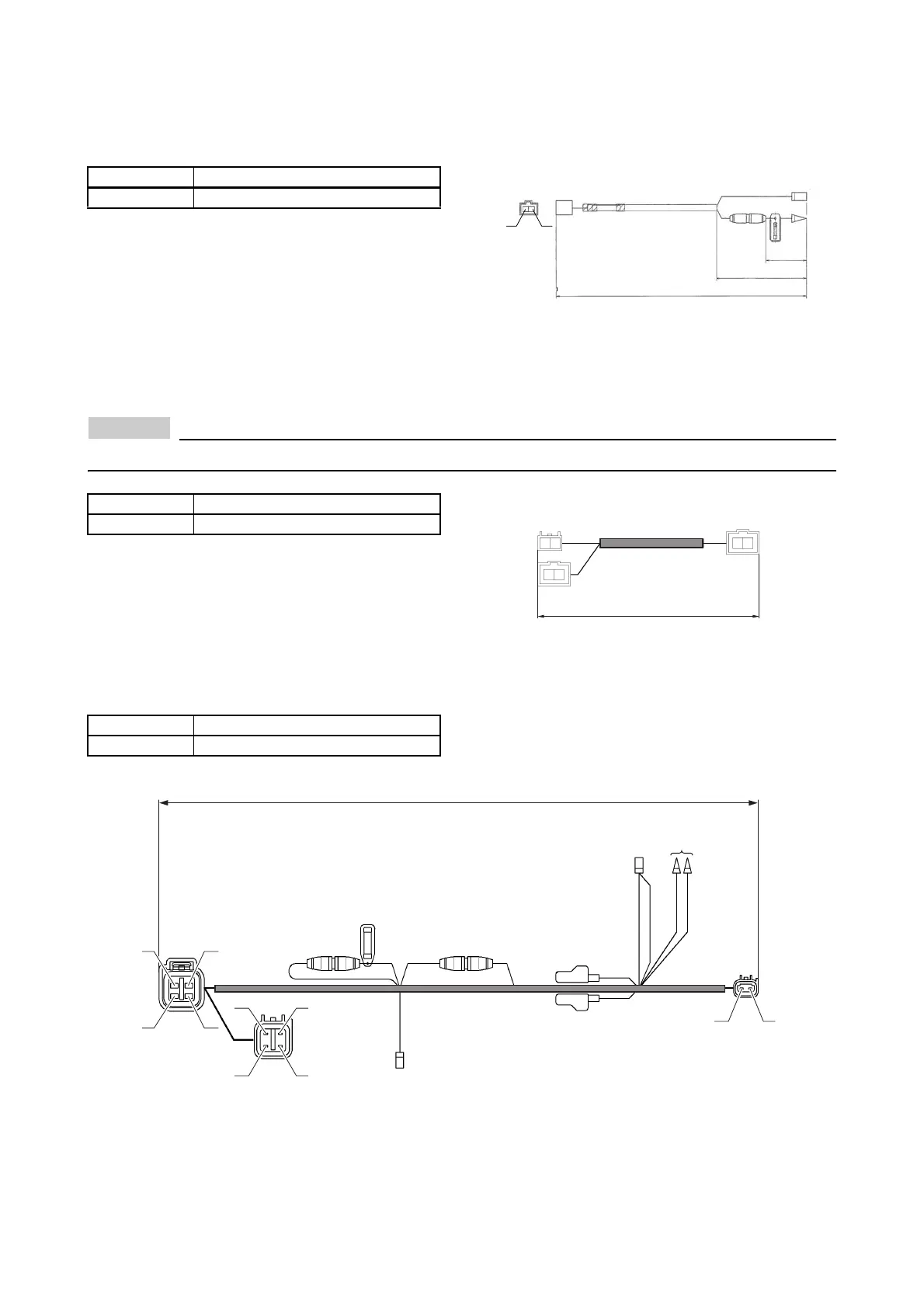
IMMOBILIZER POWER DISTRIBUTION WIRE 2
Supplies electric power to activate the immobilizer system in case of multi-engine application.
Part No. Remarks
6Y8-83553-01 Shared with 6Y8 network system
Part No. Remarks
6Y9-83553-20
Part No. Remarks
6Y8-81315-00 For start/stop button SW panel
2400 (94)
70 (2.75)
170 (6.63)
(10A)
B
(RED)
Y
B
YY
(RED)
(RED)
YB
BY
BY
(RED)
600 (23.6)
To S W
panel
To 6Y9
network
hub
To 6Y8
network hub
2400 (94.5)
To SW panel
(Twin, Triple)
To PWR supply wire
(for network system)
Fuse 5AFuse 5A
To immobilizer
unit
To network
hub
To
immobilizer
unit
To SW panel
(Twin, Triple)
(WHT)
(WHT)
(BLU)
W
RR
R
YY
Y
Y
Y
R
L
YB
LW
BX
R Y
 Loading...