Resistor braking
139
• the temperature of the room the resistor is located in does not exceed the allowed
maximum.
Supply the resistor with cooling air/water according to the resistor manufacturer’s
instructions.
WARNING! The materials near the brake resistor must be non-flammable. The
surface temperature of the resistor is high. Air flowing from the resistor is of
hundreds of degrees Celsius. If the exhaust vents are connected to a ventilation
system, ensure that the material withstands high temperatures. Protect the resistor
against contact.
Protecting the system in fault situations
Thermal overload protection
The brake chopper protects itself and the resistor cables against thermal overload
when the cables are dimensioned according to the nominal current of the drive. The
drive control program includes a resistor and resistor cable thermal protection
function which can be tuned by the user. See the Firmware Manual.
A main contactor is not required for protecting against resistor overheating when the
resistor is dimensioned according to the instructions and the internal brake chopper
is in use. The drive will disable power flow through the input bridge if the chopper
remains conductive in a fault situation. Note: If an external brake chopper (outside
the drive module) is used, a main contactor is always required.
A thermal switch (standard in ABB resistors) is required for safety reasons. The
cable must be shielded and not longer than the resistor cable.
Short-circuit protection
The input fuses will also protect the resistor cable when it is dimensioned according
to the input cable.
Selecting and routing the brake circuit cables
Use the cable type used for drive input cabling (refer to chapter Technical data) to
ensure that the input fuses will also protect the resistor cable. Alternatively, two-
conductor shielded cable with the same cross-sectional area can be used.
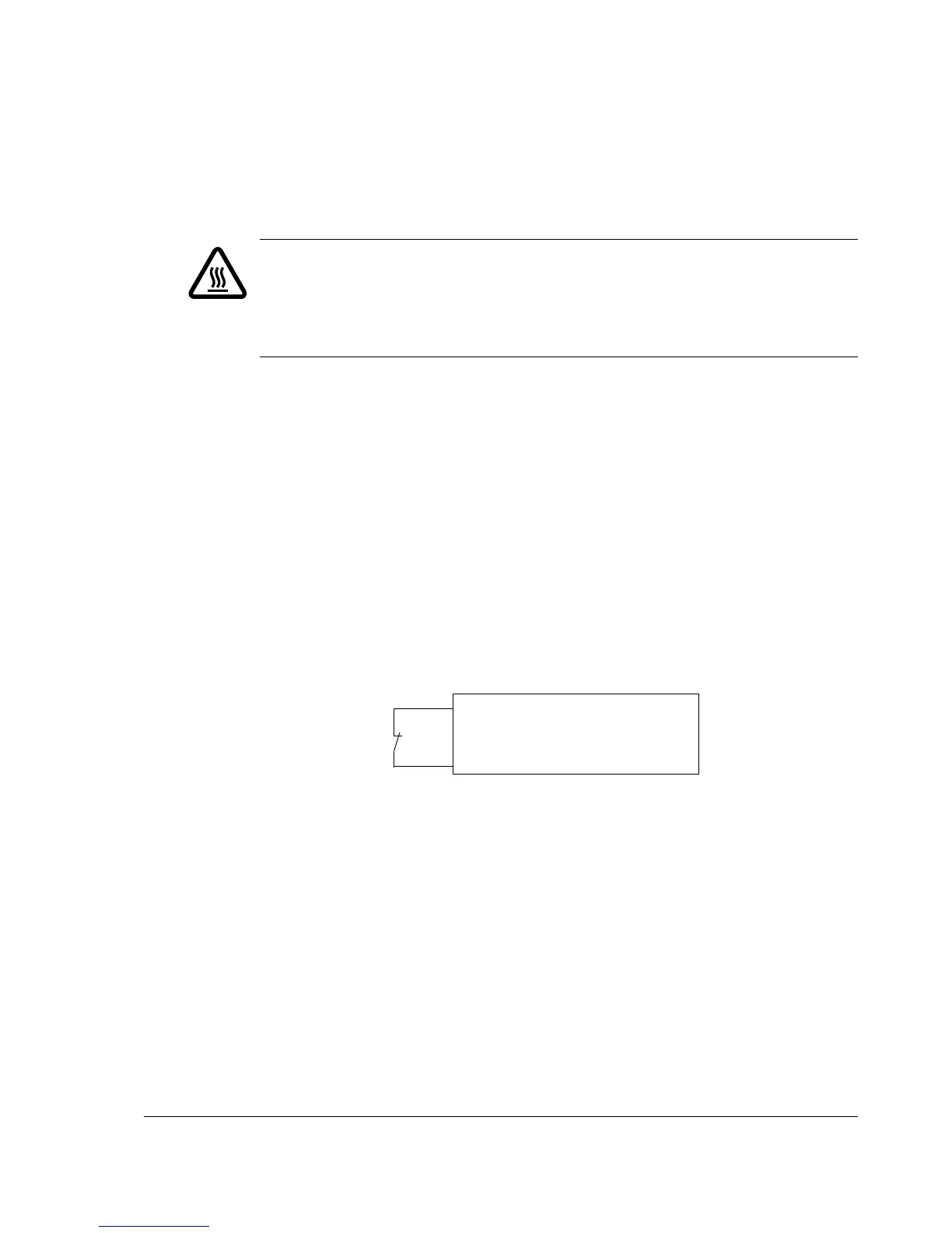
Θ
Thermal switch
(standard in ABB re-
sistors)
Digital input of the JCU Control Unit.
See the Firmware Manual for parame-
ter settings.

 Loading...


