EasyManuals Logo

ABB ACS850 Hardware Manual

ABB ACS850
145 pages
To Next Page IconTo Next Page
To Previous Page IconTo Previous Page
Page #26 background imageLoading...
Page #26 background image
Operation principle and hardware description
26
Product overview
The degree of protection of the drive module is IP00. The module must be installed
into a cabinet by the customer.
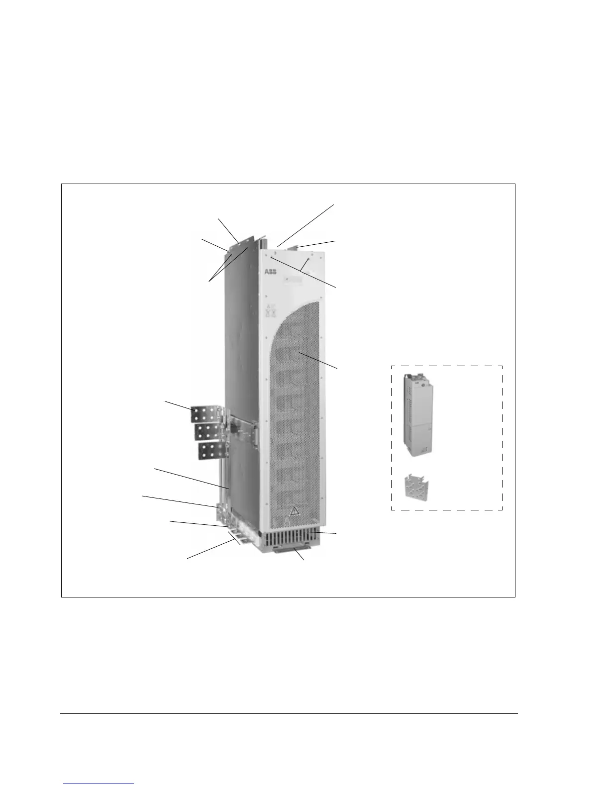
Layout
The components of the standard unit are shown below.
Front cover
Pedestal
Motor cable terminals
Input cable terminals
Busbars for connecting optional vertical brake
and DC busbars
PE terminal
Alternative output cable
terminals (when no
vertical busbars are used)
Fastening bracket
Fastening points
Fastening points
Additional holes for
fastening the cable
terminals
Control unit
(JCU)
Lifting lug
Control cable
clamp plate
Drive module
Fastening points
Cables going to the JCU Control Unit and
APOW board are coiled on the top of the
module.
Phone: 800.894.0412 - Fax: 888.723.4773 - Web: www.clrwtr.com - Email: info@clrwtr.com

Table of Contents

Other manuals for ABB ACS850

Questions and Answers:

Question and Answer IconNeed help?

Do you have a question about the ABB ACS850 and is the answer not in the manual?

ABB ACS850 Specifications

General IconGeneral
SafetySTO (Safe Torque Off)
CommunicationCANopen
EnclosureIP21
Output VoltageUp to 1000 V DC
Protection FeaturesOvercurrent, Overvoltage, Undervoltage
Cooling MethodAir or liquid cooling
Input Voltage380 to 690 V AC

Related product manuals