Operation principle and hardware description
31
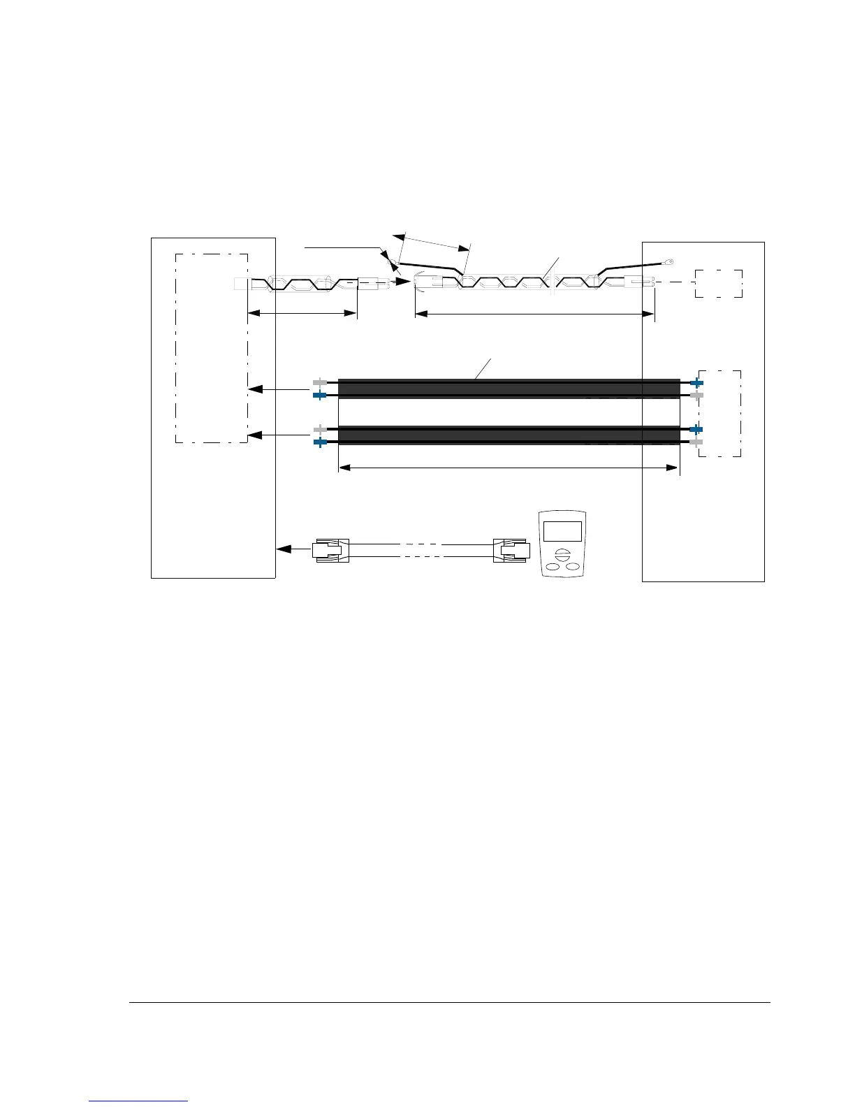
Cables for connecting the control unit to the drive module and control panel
The cables connectiong the drive module and control panel to the control unit are
shown below. See pages 86 and 87 for the actual connections.
Circuit boards
The drive contains the following printed circuit boards as standard:
• main circuit board (JINT)
• control and I/O board (JCON) inside the JCU Control Unit
• adapter board (JRIB) connected to the JCON board
• input bridge control board (AINP)
• input bridge protection board (AIBP) which includes snubbers for the thyristors
and varistors
• power supply board (APOW)
• gate driver control board (AGDR)
• diagnostics and panel interface board (JDPI)
• brake chopper control board (ABRC) with option +D150
3 m (118 in.)
JINT
APOW
3 m (118 in.)
2100 mm (83 in.)
Drive module
Protective tube
Shield
JCU Control Unit
Category 5e cable
300 mm (12 in.)
JRIB
ø
4
.
5
(
0
.
1
8
”
)
8
0
(
3
.
1
5
”
)

 Loading...


