Planning the cabinet installation
36
Planning the layout of the cabinet
Design a spacious layout to ensure easy installation and maintenance. Sufficient
cooling air flow, obligatory clearances, cables and cable support structures all
require space.
Place the control board(s) away from:
• the main circuit components such as contactor, switches and power cables
• hot parts (heat sink, air outlet of the drive module).
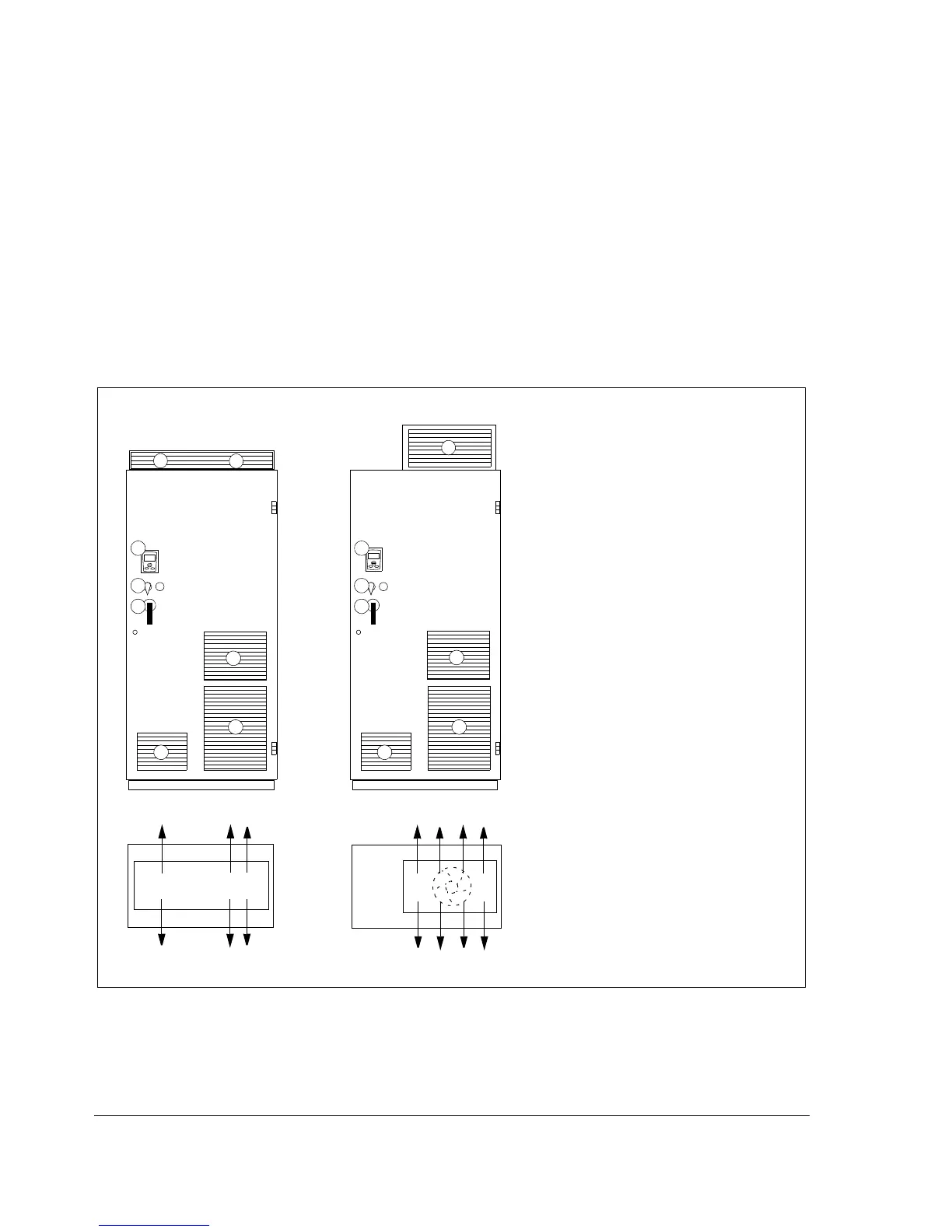
Layout examples, door closed
Layout examples for IP22 and IP54 cabinets are shown below.
1a Air inlet for the drive module
1b Air inlet for the other equipment
2a Air outlet for the drive module
2b Air outlet for the other equipment
2c Air outlet for the drive module and the
other equipment, an extra exhaust fan
3 Drive control panel (Control Panel Door
Mounting kit, +J410). The control panel
is connected to the JCU Control Unit
inside the cabinet)
4 Contactor control switch and emergency
stop switch (connected to the contactor
control circuit inside the cabinet)
5 Operating handle of the disconnector
4
5
1a
1b
IP54
4
5
1a
1b
1a
IP22
2c
2b
1a
2a
Roof air flow viewed from top
33

 Loading...


