Installation checklist
97
Groundings and protection
Checks for groundings and protections are listed below. Tips for installations where
EMC emissions must be minimised are given in column Extra requirements for EMC.
Labels, switches, fuses and doors
Checks for labels, switches, fuses and doors are listed below.
Electrical installation
Checks for electrical installation are listed below. See Planning the electrical
installation, Electrical installation.
6 Groundings and protection Extra requirements for EMC
6.1 The grounding colours, cross-section and grounding points
of modules and other equipment match the circuit diagrams.
No long routes for pigtails
6.2 Connections of PE cables and busbars are tight enough.
Pull the cable to test that it does not loosen.
No long routes for pigtails
6.3 Doors equipped with electrical equipment are grounded. No long grounding routes. From EMC standpoint
best result is achieved with a flat copper braid.
6.4 Fans that can be touched are shrouded.
6.5 Live parts inside the doors are protected against direct
contact to at least IP 2x (if required).
7Labels
7.1 The type designation labels and warning and instruction stickers are made according to the local
regulations and placed correctly.
8. Switches and doors
8.1 Check the functioning of mechanical switches, main dicsonnecting switch and cabinet doors.
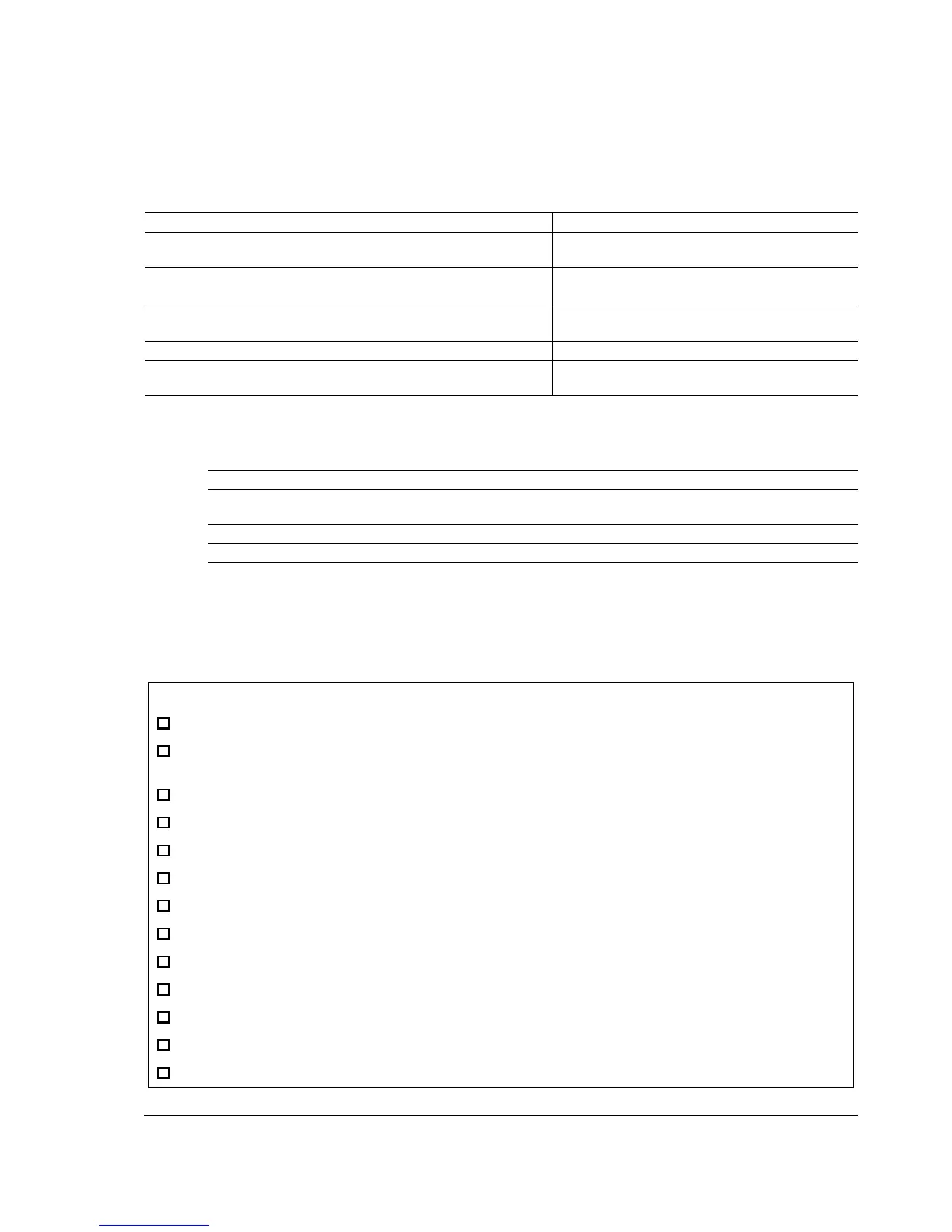
Check
The capacitors are reformed if stored over one year (ask local ABB representative for more information).
The drive is grounded properly: 1) proper and properly tightenened PE connector, 2) proper galvanic connection
between drive frame and cabinet (fastening points are unpainted).
The supply (input power) voltage matches the drive nominal input voltage.
The supply (input power) is connected to U1/V1/W1 and the terminals are tightened to specified torque.
Appropriate supply (input power) fuses and disconnector are installed.
The motor is connected to U2/V2/W2, and the terminals are tightened to specified torque.
The brake resistor (if present) is connected to R+/R-, and the terminals are tightened to specified torque.
The motor cable (and braking resistor cable, if present) is routed away from other cables.
There are no power factor compensation capacitors in the motor cable.
The external control connections to the JCU Control Unit are OK.
There are no tools, foreign objects or dust from drilling inside the drive.
The supply (input power) voltage cannot be applied to the output of the drive through a bypass connection.
Motor connection box and other covers are in place.

 Loading...


