Planning the cabinet installation
45
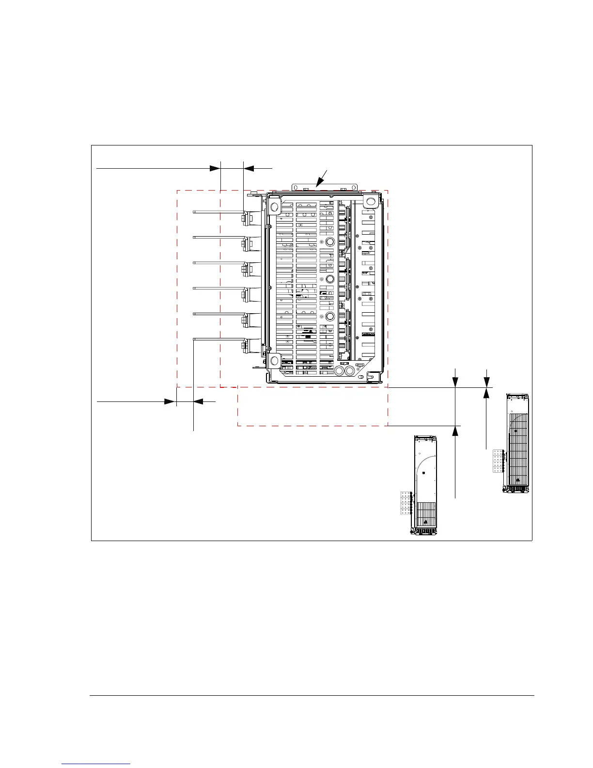
Free space at the side and front of the drive module
The figure below shows the required free space in a unit with motor and brake
busbars connected to the left-hand side of the module. The required free space
when no vertical busbars are used is also shown.
Other installation positions
Contact your local ABB representative.
0 mm (0 in.)
150 mm (5.91 in.)
100 mm (3.94 in.)
50 mm (1.97 in.)
Air inlet side
Cables connected to
the vertical output
busbar terminals
require 50 mm (1.97
in.) free space
around the busbar
terminals for
cooling.
No extra space is needed at the back.
The required free space in front of the unit
depends on the gratings in the cabinet door:
• 0 mm (0 in.) with air inlets as high as the
grating in the module 1120 mm (44 in.)
• 150 mm (5.91 in.) with air inlets at the lower
part of the cabinet only.
Cables connected
to the output
busbars of the
pedestal require
100 mm (3.94 in.)
free space around
the busbars for
cooling.

 Loading...


