Operation principle and hardware description
30
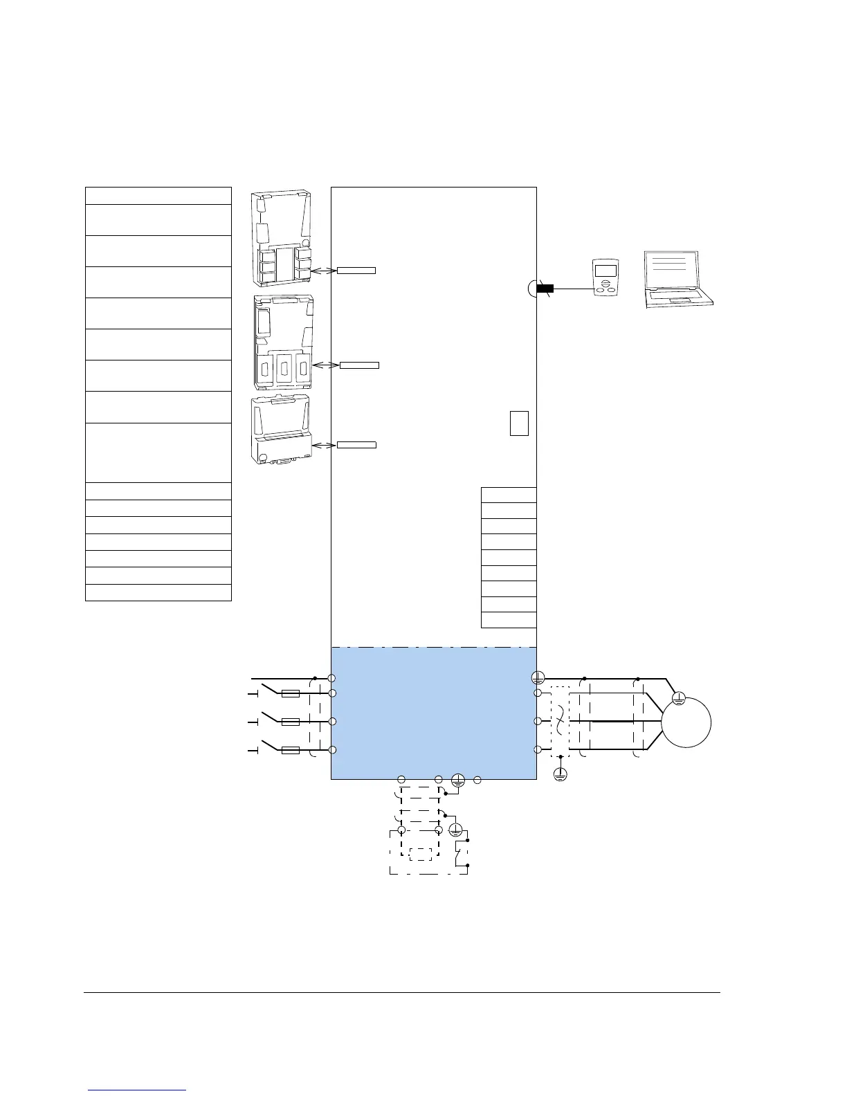
Power connections and control interfaces
The diagram shows the power connections and control interfaces of the drive.
Slot 1
Slot 2
Slot 3
Control unit (JCU)
FXX
F
X
X
X
F
X
X
Control panel or PC
Memory unit
1)
Brake resistor (optional)
Power unit
Brake
chopper
3-phase power
supply
AC motor
U1
V1
W1
L1
L2
L3
PE
PE
U2
V2
W2
t°
R-
UDC+
R+
UDC-
For intormation on default
connections, see page 87. For
specifications, see page 119.
* programmable.
Slot 1 / Slot 2
FIO-01 (Digital I/O
extension)
FIO-11 (Analog I/O
extension)
FIO-21 (Analog and digital
I/O extension) )
FEN-01 (TTL incremental
encoder interface)
FEN-11 (TTL absolute
encoder interface)
FEN-21 (Resolver
interface)
FEN-31 (HTL incremental
encoder interface)
Note: No two resolver/
encoder interfaces of the
same type can be
connected at a time
Slot 3 (Fieldbus adapter)
FCAN-0x (CANopen)
FDNA-0x (DeviceNet)
FENA-0x (Ethernet/IP)
FLON-01 (LonWorks)
FSCA-01 (Modbus)
FPBA-0x (PROFIBUS)
X7
M
3 ~
2)
du/dt or sine filter (optional,
see page 143)
2)
1)
See page 110.
External power input XPOW
*Relay outputs (3 pcs) XRO1…3
24 V DC output XD24
*Digital inputs (6 pcs) XDI
*Digital input/outputs (2 pcs) XDIO
*Analog inputs XAI
*Analog outputs XAO
Drive-to-drive link XD2D
Safe Torque Off XSTO

 Loading...


