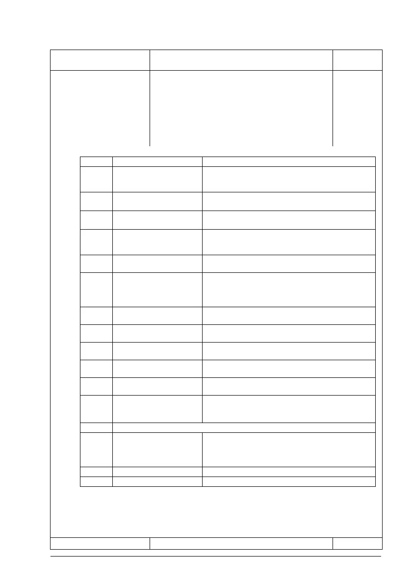
No. Name/Value Description Def/
Bit Name Information
0 Supply frequency 60 Hz 0 = 50 Hz; 1 = 60 Hz. Affects parameters 11.45, 11.59,
12.20, 13.18, 30.11, 30.12, 30.13, 30.14, 31.26, 31.27,
46.01, 46.02.
1 Emergency stop Cat 0 Emergency stop, Category 0, without FSO module.
Affects parameters 21.04, 21.05, 23.11.
2 Emergency stop Cat 1 Emergency stop, Category 1, without FSO module.
Affects parameters 10.24, 21.04, 21.05, 23.11.
3 RO2 for -07 cabinet cooling
fan
1 = Control of cabinet cooling fan (used only with
specific ACS880-07 hardware). Affects parameters
10.27, 10.28, 10.29.
4 Externally powered control
unit
1 = Control unit powered externally. Affects parameter
95.04.
5 DC supply switch 1 = DC switch monitoring active. Affects parameters
20.12, 31.03, 95.08.
Note: Setting this bit activates the Run enable signal.
Recheck 20.12 and adjust if necessary
6 DOL motor switch 1 = Motor fan control active. Affects parameters 10.24,
35.100, 35.103, 35.104.
7 xSFC-01 fuse switch
controller
1 = xSFC charging controller used. Affects parameter
95.09.
8 Service switch 1 = Service switch connected. Affects parameters 31.01,
31.02.
9 Output contactor 1 = Output contactor present. Affects parameters 10.24,
20.12.
10 Brake resistor, sine filter,
IP54 fan
1 = Status (eg. thermal) switches connected to DIIL
input. Affects 20.11, 20.12
.
11 INU-DSU communication Supply unit control by inverter unit.
1 = Yes (activates communication through RDCO
module CH1)
12 Reserved
13 Du/dt filter activation 1 = A du/dt filter is connected to the drive/inverter output.
Note: This bit is to be left at 0 if the drive/inverter module
is equipped with internal du/dt filtering (for example,
frame R8i inverter modules with option +E205).
14 DOL fan activation Reserved
15 INU-ISU communication 1 = IGBT supply unit control by inverter unit active.

 Loading...


