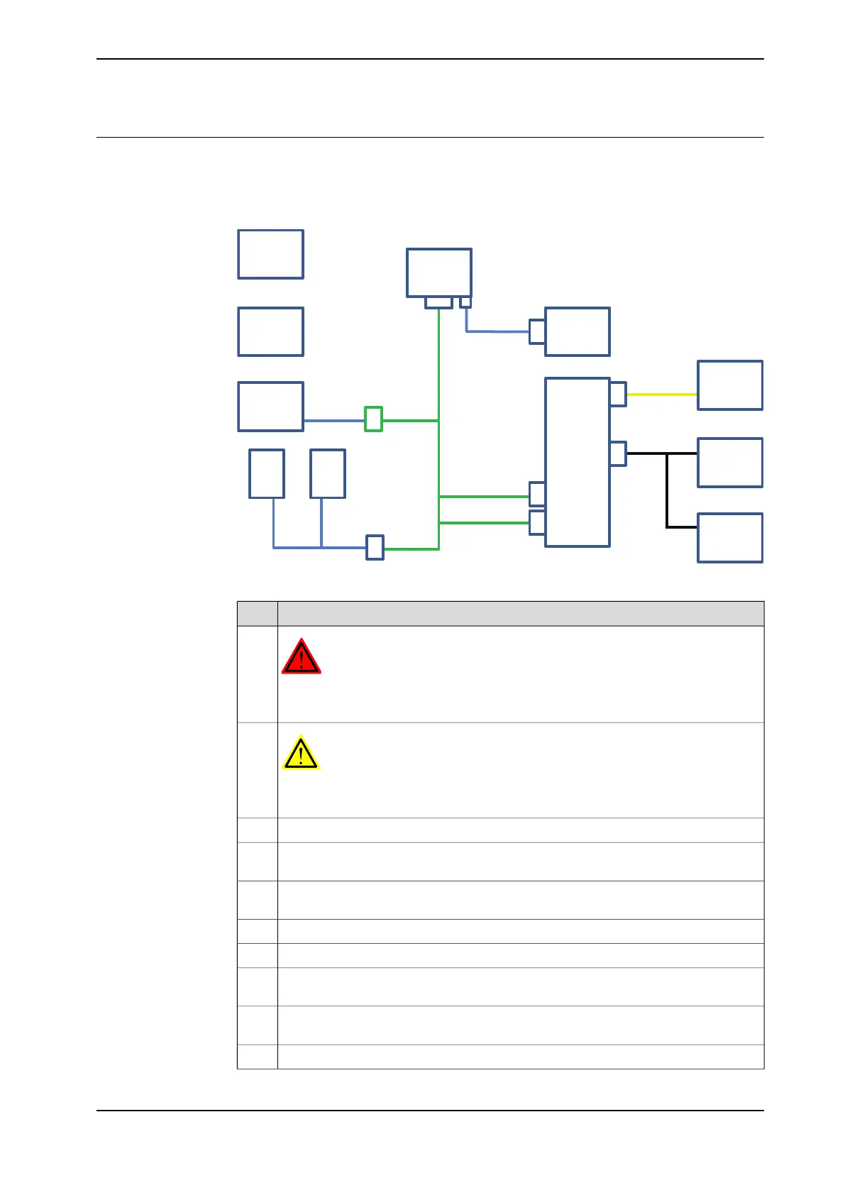
Connecting the cables to the Safety module (hardware switch and 731-1)
This procedure describes how to connect the cables for a robot controller equipped
with the options Hardware switch and 731-1 Safety internal connection.
A21
K42 K43
X14X15
A2
B
E
Safety Module
D
XS/XP38
XS/XP37
Safety Board
S21.3
S21.1
S21.2
G
EM Stop
Motors On
Key Switch
A31.4
X6 XS1
X6
X9
X3
G2
S21.3
S21.1
S21.2
E
M Stop
Motors On
Key Switch
F
xx1600000252
Action
DANGER
Before commencing any work inside the cabinet, read the safety information in
section DANGER - Make sure that the main power has been switched off! on page 33
1
WARNING
The unit is sensitive to ESD. Before handling the unit please read the safety inform-
ation in the section WARNING - The unit is sensitive to ESD! on page 34
2
Mount auxiliary contact harness contact blocks (B) on contactors K42 and K43.3
Connect auxiliary contact harness (B) to safety hard Key switch harness (A2) at
connector XS/XP38.
4
Connect safety hard Key switch harness (A2) connector A31.4.X6 to Safety board
DSQC1015.
5
Connect connector A31.4.X1 on 24 V I/O harness (D) to safety board DSQC1015.6
Connect connector G2.X3 on 24 V I/O harness (D) to power distribution unit (G2).7
Connect safety hard Key switch harness (A2) connectors X14 and X15 to the panel
board (A21).
8
Connect extended Key switch harness (G) to safety hard Key switch harness (A2)
at connector XS/XP37.
9
Connect emergency stop harness (E) connector A21.X9 to the panel board.10
Continues on next page
Product manual - IRC5 Compact 107
3HAC047138-001 Revision: G
© Copyright 2009-2017 ABB. All rights reserved.
2 Installation and commissioning
2.11.3 Installing the Safety module DSQC1015 for SafeMove
Continued

 Loading...