ABB | SACE Emax 2
Electronic accessories | 2 - Ekip Link module
63 | © 2014 ABB | 1SDH000999R0002 - L8569
Connections
The modules must be mounted on the terminal box of the circuit-breaker or of the fixed part of the withdrawable
circuit-breaker, in the first free slot.
Information on the assembly is available from the web site http://www.abb.com/abblibrary/DownloadCenter/,
in particular in the kit sheet 1SDH001000R0511.
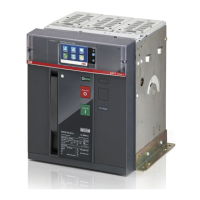
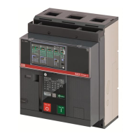
An example with an E1.2 circuit-breaker in fixed and withdrawable versions is provided to the side.
The following is a view of the terminal block of the E1.2 circuit-breaker and the wiring diagram:
R2
R1
U2
U1
38
36
35
98
96
95
YRMS33S51
YO
EKIP SupplyTrip Unit I/O
Ge-
Ge
Szc
K2
K1
W4
W3
Q4Q3Q2Q1YC
YU
YO2
RTC
I/O
TU
44
42
41
34
32
31
24
22
21
14
12
11
C12
C13
C11
C2
C3
C1
D2
D1
48
46
45
Ne
Rca
Ne-
Gzi
Szo
Szi
Gzo
Rct
Vn
V1
V2
V3
Module Module
X
A4
XV
A3
XV
X
A4
32
Uaux.
K1
K1
K1
K2
K2
K2
110-240VAC/DC
+/L
-/N
W3
W3 W4
(B)(A)
W2 (LOCAL BUS)
W3 W4
W4
24-48VDC
Ekip Supply 24-48VDC
Ekip Supply 110-240VAC/DC
*
Q)
SUPPLY
K51
* A), * I)
Diagrams 32
For external wiring, AWG 22-16 cables with a maximum external diameter of 1.4 mm must be used.
Further information is available on page 58, or on the site http://www.abb.com/abblibrary/DownloadCenter/,
where the wiring diagram is available 1SDM000091R0001.
Signallings
The following table illustrates the possible signals, and their meaning:
Pos. Description
A
Power LED, green. The possible states are:
•Off:powersupplyabsent.
•Onxed:powersupplypresent.
2 - Ekip Link module
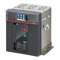
Description
Ekip Link is a communication accessory module that integrates the circuit-breaker in an internal Ethernet
network with an ABB proprietary protocol.
The network to which the module is to be connected must be dedicated and comprising only Ekip Link and
Ethernet switches that declare support for level L2 multicast on the datasheet. In this case the Ethernet
switches do not require any configuration. If, instead, the network also includes routers, multicast must be
enabled and configured on all VLAN interfaces with level L3.
IMPORTANT: the module can be connected only to internal Ethernet networks with
one or more switchboards, to which releases or ABB Emax 2 accessories are
connected. It is the installer's responsibility to ensure that all the necessary safety
measures are adopted for all the connected devices (for example, the necessary
access authorisations, and so on). The module cannot be connected to other Ethernet
networks (for example, with the purpose of monitoring the system, or the office), or
to the Internet.
The module is necessary if you wish to implement these functions:
• Power Controller.
• Zone Selectivity.
• Programmable Logic.
For these functions, the releases of the system tat are involved must be equipped with an Ekip Link, and for
each of these the IP addresses of the Ekip Link modules of the other releases must be inserted.
Each Ekip Link can be interfaced with a maximum of 15 releases (actors), including at most 12 for the Zone
Selectivity function.
Only with Ekip Dip releases, the module can also be used with a function similar to that one of the Ekip
Com Modbus TCP module, but with possibility to communicate only with an ABB master (for example: Ekip
Connect or Ekip Control Panel).
IMPORTANT: only one Ekip Link can be installed on each circuit-breaker.
The modules are always supplied with Ekip AUP and Ekip RTC contacts (see the chapter "4 - Other
accessories" on page 67).
Compatibility and power supply
The module can be installed in the presence of Ekip Dip, Touch, Hi-Touch, G Touch, and G Hi-Touch releases,
and requires the presence of an Ekip Supply module in the first slot of the circuit-breaker terminal box.
 Loading...